





Issue: The machine cannot communicate with the control software.
Communication Methods
The machine supports three communication methods:
| Method | Description |
|---|---|
| A. USB Cable | Direct USB connection between machine and PC |
| B. Ethernet Cable | Network cable connection between machine and PC |
| C. USB Drive | Offline file transfer via USB flash drive |
A. USB Cable Communication Failure
Step-by-Step Diagnostic Procedure
Please complete each step in order. Only proceed to the next step after the current issue has been ruled out.
Step 1: Check USB Cable Connection
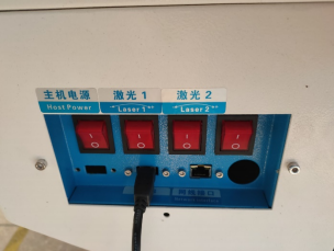
Ensure the USB cable is securely connected to both the machine and the PC.
Check for any visible damage to the cable or connectors.
Try using a different USB port on the PC if available.
A loose or damaged USB connection is the most common cause of communication failure. Always verify physical connections first.
Step 2: Verify Driver Installation
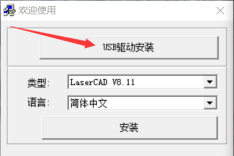
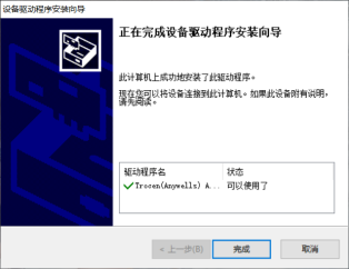
The software requires a specific USB driver to communicate with the machine.
If the driver was not installed during software setup, the machine will not be recognized.
Check the Windows Device Manager for any unrecognized devices or yellow warning icons.
Reinstall the driver if necessary (refer to the software installation guide).
Driver issues often occur when the software is installed after the USB cable is connected, or when the driver is blocked by antivirus software. Install the driver first, then connect the cable.
Step 3: Check Communication Settings in Software
Open the control software and verify that the correct communication settings are configured:
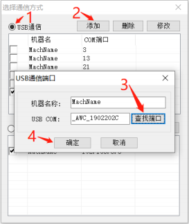
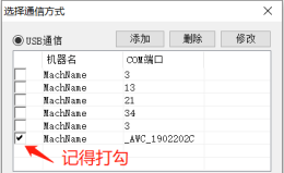
In the software, click on the Communication Settings menu.
In the pop-up window, select USB Communication.
Click Add.
In the new pop-up window, click Find Port.
You should see a port code similar to
_AWC_1902202C(as shown in the figure).Select the detected port and click OK to complete the connection.
If the port does not appear in the list, the driver may not be installed correctly, or the USB cable may not be properly connected.

B. Ethernet Cable Communication Failure
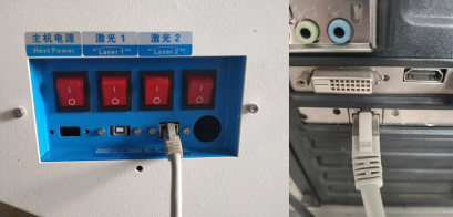
Step 1: Check Ethernet Cable Connection
Ensure the Ethernet cable is securely connected to both the machine and the PC.
Check for any visible damage to the cable or connectors.
Verify that the network port indicator lights on both ends are active.
A loose or damaged network cable can prevent communication. Always verify physical connections first.
Step 2: Configure PC Network IP Address
The PC and the machine must be on the same subnet for communication to work.
Open the Local Area Connection (Ethernet) settings on your PC.
Access the Internet Protocol Version 4 (TCP/IPv4) properties.
Set the PC's IP address as follows:
The first three segments must match the machine's IP address (displayed on the machine's control panel).
The fourth segment must be different from the machine's IP address.
| Example | Machine IP | PC IP (Suggested) |
|---|---|---|
| Setting | 192.168.8.1 | 192.168.8.2 |
Ensure the subnet mask is set to 255.255.255.0. IP address configuration may vary slightly depending on your operating system version.
Step 3: Configure Software Communication Settings
After setting the PC's IP address, configure the software accordingly:
Open the control software (LaserCAD).
Navigate to the Communication Settings menu.
Select Ethernet Communication.
Enter the machine's IP address (as shown on the control panel).
Click Connect to establish communication.
If the software cannot connect, verify that the machine's IP address is correctly entered and that no firewall is blocking the connection.
C. USB Drive (Offline) File Transfer
This method does not require real-time communication between the machine and PC. Instead, files are saved to a USB drive and transferred offline.
Procedure:
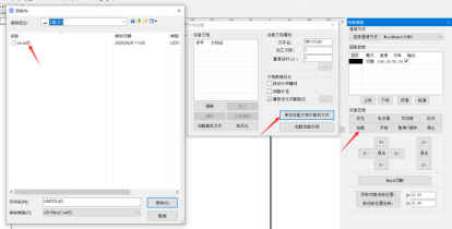
Open LaserCAD and set up the processing parameters for your graphic.
Click Load.
In the pop-up window, click Save Current Document as Offline File.
Save the file to the root directory of the USB drive.
Insert the USB drive into the USB port on the machine's control panel.
On the machine panel, navigate to: Menu → USB File → Copy File to Machine.
Select the file and start the job.
Important: The working file format must be
.ud5. Files saved in other formats will not be recognized by the machine.
Communication Method Quick Reference
| Method | When to Use | Key Checkpoints |
|---|---|---|
| USB Cable | Real-time control from PC | Cable connection, driver installation, port selection |
| Ethernet | Real-time control from PC | Cable connection, IP address matching, software settings |
| USB Drive | Offline operation without PC | File format must be .ud5, save to USB root directory |
Still Having Issues?
If communication cannot be established after completing all the above steps, please contact our technical support team with the following information:
Machine model number
Software version (LaserCAD version)
Operating system version (Windows 7/10/11)
Communication method attempted (USB / Ethernet / USB Drive)
Screenshot of the error message or port detection window
Device Manager screenshot (for USB driver issues)
We will respond within 24 hours to assist you.
【Details】
Issue: The X or Y axis does not move smoothly, moves abnormally, or fails to operate altogether.
Possible Causes
This issue is typically caused by one of the following factors:
Drive connection issues
Jitter or stuttering during motion
Limit switch failure
Step-by-Step Diagnostic Procedure
Please complete each step in order. Only proceed to the next step after the current issue has been ruled out.
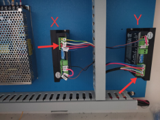
Step 1: Check Axis Drive Status
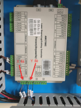
Inspect the status indicator lights on the drive modules for each axis.
| Indicator Status | Diagnosis | Action Required |
|---|---|---|
| Green light ON | Drive is working normally | Proceed to next step |
| Red light ON | Drive or motor may be faulty | Check drive connections, wiring, or replace the drive/motor if necessary |
PS: Green light indicates normal operation; Red light indicates a potential issue with the driver or motor.
Step 2: Inspect Pulleys and Belt Tension
Over time, dust, debris, or wear can affect the mechanical transmission components, leading to motion issues.
Check the pulleys, belts, and gears for signs of wear, looseness, or misalignment.
Ensure the belt tension is properly adjusted – not too loose (causing slipping) and not too tight (causing excessive load).
Clean all transmission components regularly to prevent debris or particle buildup that may obstruct smooth movement.
Regular cleaning and inspection of pulleys, belts, and gears are essential to maintain motion accuracy and prevent unexpected faults.
Step 3: Check Limit Switch Functionality
Limit switches are critical for defining the machine's travel boundaries. A faulty limit switch can cause the axis to fail to stop at the correct position.
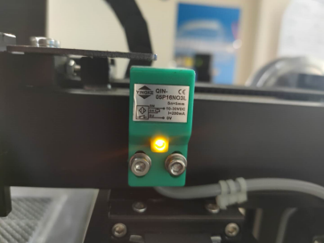
Test Procedure:
Place a metal plate (or iron piece) on the sensing surface of the limit switch.
Observe the indicator light on the limit switch:
| Observation | Diagnosis | Action Required |
|---|---|---|
| Light does NOT turn on | Limit switch wiring is faulty or the switch itself is damaged | Replace the limit switch or test by swapping with the cable inside the drag chain |
| Light turns ON | Limit switch is functioning; check the metal sensing plate height | Adjust the sensing plate on the slider so that the gap between the plate and the limit switch is approximately 1mm |
The sensing gap between the metal plate and the limit switch should be about 1mm for reliable detection. If the gap is too large or too small, the limit switch may fail to trigger properly.
Summary Checklist
| Step | Checkpoint | Status |
|---|---|---|
| 1 | Drive indicator light – Green (OK) / Red (Fault) | ☐ OK / ☐ Fail |
| 2 | Pulleys, belts, and gears – clean and properly tensioned | ☐ OK / ☐ Fail |
| 3 | Limit switch – light responds to metal plate | ☐ OK / ☐ Fail |
| 4 | Limit switch – sensing gap ~1mm | ☐ OK / ☐ Fail |
Still Having Issues?
If the X/Y axis motion issue persists after completing all the above steps, please contact our technical support team with the following information:
Machine model number
Which axis is affected (X, Y, or both)
Photos or video of the motion behavior
Drive indicator status (Green/Red)
We will respond within 24 hours to assist you.
【Details】
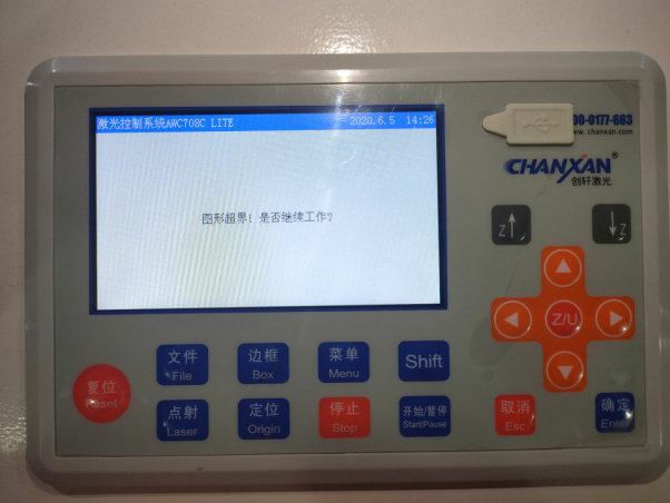
Issue: The control panel shows a "Graphic Out of Bounds" alarm.
Possible Causes
This alarm is typically triggered by one of the following three conditions:
Graphic size exceeds the machine's working area
Incorrect start point setting
Incorrect graphic relative position setting
Cause 1: Graphic Size Exceeds Working Area
Each machine has a defined maximum working area (e.g., 900×600 mm). If the graphic you are trying to process exceeds these dimensions, the machine will trigger an alarm as it cannot operate beyond its physical limits.
Always verify that your graphic dimensions fit within the machine's specified working area before starting a job.
Cause 2: Incorrect Start Point Setting
An improperly set start point may cause the graphic to extend beyond the machine's boundaries, even if the graphic itself is within size limits.
Review and reset the start point to an appropriate position within the working area.
Ensure the start point is set correctly before initiating the job.
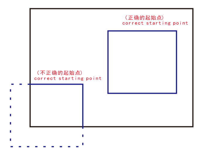
The start point determines where the machine begins processing. An incorrect start point can push the graphic outside the effective working range.
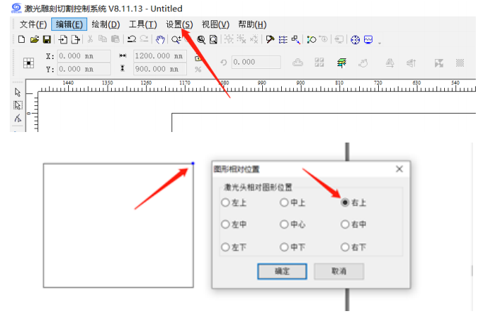
Cause 3: Incorrect Graphic Relative Position Setting
The software's default reference point may not align with your intended processing area.
Navigate to: Settings → Graphic Relative Position
In the pop-up window, select the appropriate reference point (e.g., Top Right).
A blue dot will appear at the selected corner of your graphic to indicate the current reference position.
The relative position setting defines where the software anchors the graphic. Selecting the correct reference point ensures the graphic is properly positioned within the working area.
Summary – Graphic Out of Bounds
| Checkpoint | Action |
|---|---|
| Graphic size | Confirm dimensions are within machine working area |
| Start point | Reset to a valid position within the working area |
| Relative position | Select correct reference point in software settings |
Still Having Issues?
If the alarm persists after completing all the above steps, please contact our technical support team with the following information:
Machine model number
Screenshot of the alarm displayed on the control panel
Software version being used
Description of the graphic (size, material, and settings)
We will respond within 24 hours to assist you.
【Details】
Issue: The machine is powered on but the laser does not emit a beam during operation.
Step-by-Step Diagnostic Procedure
Please complete each step in order. Only proceed to the next step after the current issue has been ruled out.
Step 1: Verify Chiller Power Status
Ensure that the water chiller is powered on and operating normally.
Check that the chiller display is active and showing normal temperature readings.
Confirm that the water circulation is running properly.
The laser tube will not fire if the chiller is not powered on, as the interlock protection system is triggered.
Step 2: Check Optical Path Alignment
Inspect whether the laser beam path is properly aligned.
Verify that all mirrors are securely mounted and not loosened during transportation or operation.
Check for any visible beam deviation or misalignment.
Optical path misalignment is a common cause of no laser output. If the beam does not reach the laser tube outlet, realignment is required.
Step 3: Test Laser Pulse via Control Panel
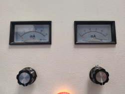
Turn the black rotary knob (power adjustment) fully clockwise to the maximum position.
Press the "TEST" button on the control panel.
Observe the following:
Whether the ammeter (current meter) shows a reading.
Whether the laser tube emits a visible flash (indicating laser generation).
If the ammeter shows no reading and the tube does not flash, the issue may lie with the control signal or laser power supply.
Step 4: Check Laser Power Supply Status
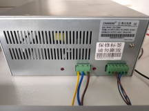
Confirm that the laser power supply is receiving power and functioning properly.
Ensure the laser power switch is turned on.
Check the power supply unit for:
Indicator light – should be illuminated.
Cooling fan – should be spinning.
If the indicator light is off or the fan is not rotating, the power supply may not be receiving input power or may be defective.
Step 5: Verify File Parameter Settings
Incorrect software parameters can prevent the laser from firing.
Open the current processing file and check the power setting.
Reset the processing power to 20% and restart the job.
Some machines require a minimum power threshold to trigger laser emission. Setting the power too low may result in no output.
Step 6: Test Laser Power Supply Directly (Hardware Test)
Perform a direct hardware test on the laser power supply:
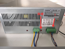
Important: Before proceeding, disconnect the green terminal block (Pin 1) as shown in the diagram below.
Press the "TEST" button on the laser power supply itself.
Observe whether the laser tube emits a laser flash.
If the laser fires during this direct test, the power supply is functioning correctly and the issue may be related to the control signal or wiring. If it still does not fire, the power supply or laser tube may be faulty.
(Please refer to the attached diagram for the location of the green terminal block.)
Test Results Summary
After completing all the above steps, please document and report the following results to our technical support team:
| Step | Test Performed | Result (Pass / Fail / Note) |
|---|---|---|
| 1 | Chiller power status | |
| 2 | Optical path alignment | |
| 3 | Panel TEST button – ammeter reading | |
| 3 | Panel TEST button – laser flash | |
| 4 | Power supply indicator & fan | |
| 5 | Parameter reset to 20% | |
| 6 | PSU direct TEST (green terminal removed) |
Still Having Issues?
If the laser still does not fire after completing all the above steps, please contact our technical support team with the completed test results table above, along with:
Machine model number
Laser tube model and wattage
Photos or video of the control panel and power supply during testing
We will respond within 24 hours to assist you.
【Details】
Issue: The fume extraction system performs poorly, with smoke not being effectively drawn away from the cutting area.
Possible Causes
This issue is typically caused by one of the following two conditions:
Insufficient sealing of the worktable
Dust accumulation and blockage in the extraction path
Step-by-Step Diagnostic Procedure
Please complete each step in order. Only proceed to the next step after the current issue has been ruled out.
Step 1: Check Worktable Sealing
During operation, ensure that all areas of the worktable except the cutting zone are properly covered or sealed.
Use auxiliary cover plates or masking materials to minimize air leakage.
Proper sealing creates negative pressure that concentrates extraction efficiency directly at the cutting point.
Better sealing around the worktable significantly improves fume capture performance, especially for small or localized cutting areas.
Step 2: Inspect Extraction Path for Dust Blockage
Over time, dust and debris can accumulate along the extraction channel, restricting airflow and reducing suction power.
Regularly clean the following areas:
Dust collection drawer
Machine air intake (suction port)
Fan / blower intake port
Perform maintenance cleaning on a regular basis to prevent dust buildup that can obstruct the extraction path and impair system performance.

Recommended Maintenance Schedule
| Component | Frequency |
|---|---|
| Dust collection drawer | Check and empty daily |
| Machine suction port | Clean weekly |
| Fan intake port | Clean weekly |
| Full extraction system inspection | Monthly |
Still Having Issues?
If the extraction performance does not improve after completing all the above steps, please contact our technical support team with the following information:
Machine model number
Description of materials being processed (type and thickness)
Photos of the worktable setup and extraction path
We will respond within 24 hours to assist you.
【Details】
Issue: The air pump fails to start or does not operate normally.
Possible Causes
This issue is typically caused by one of the following two conditions:
Air pump malfunction
Kinked air hose or closed air flow control valve
Step-by-Step Diagnostic Procedure
Please complete each step in order. Only proceed to the next step after the current issue has been ruled out.
Step 1: Check Air Pump Functionality
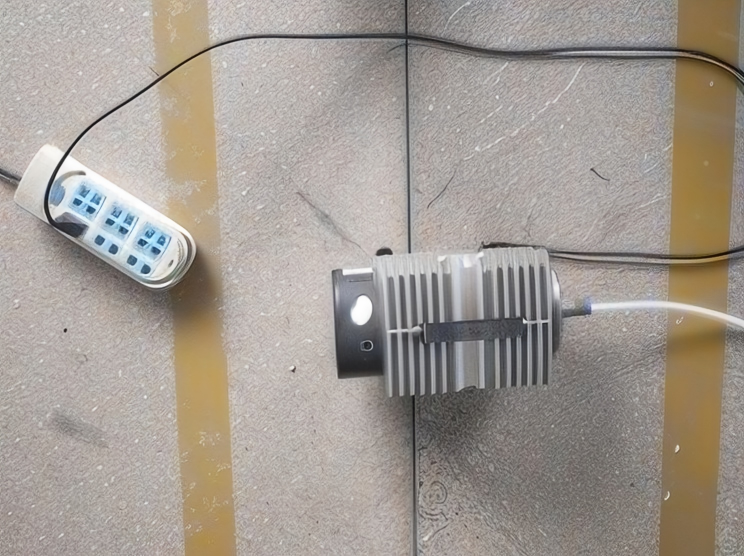
To determine whether the air pump itself is operating properly:
Disconnect the air hose from the pump outlet.
Plug in the power supply and turn on the pump.
Observe whether air is being discharged from the outlet as expected.
If no air flow is detected at the outlet, the pump may be defective and require replacement or servicing.
Step 2: Inspect Air Hose and Air Flow Control Valve
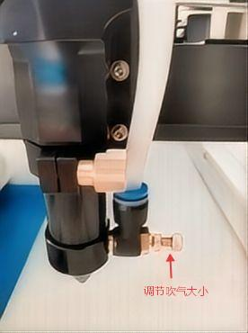
If the pump is functioning normally, examine the entire air delivery path:
Check whether the air hose is pinched, bent, or kinked anywhere along its length.
Ensure the hose is clear and unobstructed for smooth air flow.
Verify that the air flow control valve (regulator) is fully open and not accidentally closed.
Even a partially kinked hose or partially closed valve can significantly reduce or cut off air delivery.
Summary Checklist
| Step | Checkpoint | Status |
|---|---|---|
| 1 | Air pump outlet produces air flow when powered on | ☐ OK / ☐ Fail |
| 2 | Air hose is free of kinks, pinches, or obstructions | ☐ OK / ☐ Fail |
| 3 | Air flow control valve is properly open | ☐ OK / ☐ Fail |
Still Having Issues?
If the air pump still does not operate after completing all the above steps, please contact our technical support team with the following information:
Machine model number
Air pump model (if available)
Photos or video of the setup and issue
We will respond within 24 hours to assist you.
【Details】
Issue: The water chiller emits a continuous beeping alarm, but no error code is displayed on the control panel.
Possible Causes
This alarm is typically triggered by one of the following three conditions:
Low water level
Blocked water hose
Overheating alarm
Step-by-Step Diagnostic Procedure
Please complete each step in order. Only proceed to the next step after the current issue has been ruled out.
Step 1: Check Water Level
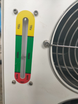
Ensure the water level is maintained within the green zone on the water reservoir. A level below this range may trigger a low-water alarm and compromise cooling performance.
Maintain water level within the green zone at all times to prevent insufficient cooling.
Step 2: Inspect Water Circulation
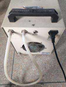
Perform a bypass test by temporarily connecting the water inlet and outlet ports with a short hose to form a closed loop.
Observe the alarm status:
| Alarm Status | Diagnosis | Action Required |
|---|---|---|
| Alarm stops | Blockage exists in the water line between the chiller and the laser tube | Inspect and clear the water hose channels inside the machine |
| Alarm persists | Check water flow through the bypass hose | If flow is intermittent or absent, the water pump or internal circulation system may be faulty |
Step 3: Examine the Cooling Vents
If the alarm is related to overheating:
Clean the dust filters / ventilation grilles on both sides of the chiller to ensure proper heat dissipation.
Verify that the coolant level is sufficient.
Place the chiller in a cool, dry, and well-ventilated location, away from direct sunlight or heat sources.
Poor ventilation or low coolant can lead to overheating and trigger the alarm.
Important Notes
| Item | Description |
|---|---|
| Water quality | Using tap water or untreated water may cause scale buildup, leading to hose blockages and potential equipment damage. We strongly recommend using distilled water or deionized water and replacing it periodically. |
| Hose connections | Ensure correct piping: • INLET port → connects to the laser device's water outlet • OUTLET port → connects to the laser device's water inlet |
Still Having Issues?
If the alarm persists after completing all the above steps, please contact our technical support team with the following information:
Chiller model number
Photos of the installation setup
Description of any recent changes or incidents
We will respond within 24 hours to assist you.
【Details】
1) The double focal length laser cutting head is a fragile item on the laser cutting machine, which is used for a long time, resulting in damage to the laser cutting head.
2) Check the straightness of the track of the fiber laser cutting machine and the verticality of the machine every six months, and find that the maintenance and debugging are not normal. If you don't do this, it is possible that the effect of cutting out is not so good, the error will increase, and the cutting quality will be affected. This is a top priority and must be done.
3) Use a vacuum cleaner to absorb dust and dirt from the machine once a week. All electrical cabinets should be kept clean and dustproof.
4) Always check the fiber strip of the fiber laser cutting machine, and ensure that it is tight. Otherwise, if there is a problem in the operation, it may hurt people and seriously lead to death. The steel strip looks like a small thing, and the problem is still a bit serious.
5) The guide rails of the fiber laser cutting machine should be cleaned frequently to eliminate dust and other debris, to ensure that the normal rack of the equipment should be wiped regularly, and the lubricating oil is added to ensure lubrication without debris. The guide rails should be cleaned and lubricated frequently, and the motor should be cleaned and lubricated frequently. The machine can move better during the process of travel, more accurate cutting, and the quality of the cut products will be improved.
【Details】
When the laser cutting machine is working, it is very dangerous if the fault occurs. The novice must be trained by the professional to operate independently. According to the experience, 13 details of the safety work of the laser cutting machine are summarized:
1. Observe the safe operation rules of general cutting machines. Start the laser in strict accordance with the laser start-up procedure.
2. Operators must be trained to familiarize themselves with the structure, performance, and knowledge of the operating system.
3. Wear protective equipment as required, and wear protective glasses that meet the requirements in the vicinity of the laser beam.
4. Do not process a material before it can be irradiated or heated with a laser to avoid the potential hazard of smoke and steam.
5. When the equipment is started, the operator must not leave the post or the person to be in charge. If it is necessary to stop, stop or cut off the power switch.
6. Keep the fire extinguisher at your fingertips; turn off the laser or shutter when not working; do not place paper, cloth, or other flammable materials near the unprotected laser beam.
7. When an abnormality is found during processing, it should be stopped immediately, and the fault should be eliminated or reported to the supervisor in time.
8. Keep the laser, bed and surrounding area clean, orderly, and free of oil, and stack the workpiece, sheet, and waste as required.
9. When using gas cylinders, avoid welding the welding wires to avoid leakage accidents. The use and transportation of gas cylinders should comply with the gas cylinder inspection procedures. Do not expose the cylinder to sunlight or heat sources. When opening the bottle valve, the operator must stand on the side of the bottle mouth.
10. Observe high pressure safety regulations when servicing. Every 40 hours of operation or weekly maintenance, every 1000 hours of operation or every six months of maintenance, in accordance with the regulations and procedures.
11. After starting the machine, the machine should be started in the low speed X and Y directions to check if there is any abnormality.
12. After entering the new part program, you should try it out and check its operation.
13. When working, pay attention to observe the operation of the machine so as to avoid the cutting machine from coming out of the effective range or two accidents.
Note: The above description is the basic principle, and it is necessary to formulate implementation according to its own situation.
【Details】
It is the most basic requirement to understand the setting of the cutting equipment system of the company and the role of each system and the process effect to be achieved;
Familiar with the main structure and function of the cutting machine and its operation precautions and methods in the production process, especially matters directly related to the process effect, such as: control of the operation panel, application of cutting software, etc.;
Master the meaning of each technical parameter of the cutting machine and its relationship with the cutting effect, and memorize the equipment configuration of the cutting parameters of each system of the company, so as to cooperate well in operation. If the parameters are equipped to make the cutting soft, the joint speed is operated. It is necessary to release it properly so as to avoid edge unevenness when cutting the soft material;
Master the professional method of measuring the cutting effect to ensure the cutting effect of various processes;
Master the operation adjustment method of the cutting machine when the materials quality, process flow, finished product requirements, new and old materials, and climatic conditions change, to ensure the stability of product quality.
【Details】
1. High precision: It is suitable for cutting of precision parts and fine cutting of various craft words and paintings.
2, Fast: more than 100 times the line cutting.
3. The heat affected zone is small and not easily deformed. The slits are smooth and beautiful, and no post-processing is required.
4, The price is very high: the price is only 1/3 of the same performance CO2 laser cutting machine, and the equivalent of 2/5 of the CNC punch.
5, The use of low cost: only 1 / 8 ~ 1/10 of the same CO2 laser laser cutting machine.
6, The follow-up maintenance costs are very low: only 1/10 ~ 1 / 15 of the same kind of CO2 laser cutting machine, and 1/3 ~ 1/4 of the equivalent efficiency CNC punching machine.
7, Stable performance, to ensure continuous production. Solid YAG lasers are one of the most stable and mature products in the laser field.
8. Compared with CNC punching machine, YAG laser cutting machine has the following advantages:
(1) It can complete the processing of various complicated structures, and the machine can complete the processing as long as any image can be drawn on the computer.
(2) No need to open the mold, only the figure is made on the computer, the product can be released immediately, that is, the new product can be developed quickly, and the cost can be saved.
(3) YAG cutting machine has automatic tracking system, so it can complete plane cutting, and can also complete all kinds of uneven surface cutting.
(4) The complicated process requires that the CNC punching machine is difficult to complete, and laser cutting can be done.
(5) The surface is very smooth, the product grade is very high, and the CNC punching machine is difficult to do.
(6) The formed box (within 0.5 m thick) needs to be treated with holes and holes, and the CNC punch can not be processed. The YAG CNC metal laser cutting machine can solve it.
【Details】
1. First, we must figure out the production range, processing materials and thickness of the cutting company, so as to determine the type, format and quantity of the equipment to be purchased, and make a simple preparation for the later procurement work. Laser cutting machine applications include mobile phones, computers, sheet metal processing, metal processing, electronics, printing, packaging, leather, clothing, industrial fabrics, advertising, crafts, furniture, decoration, medical equipment and many other industries. The mainstream in the market is 3015 and 2513, that is, 3 meters by 1.5 meters and 2.5 meters by 1.3, but this is not a problem. Generally, the company will be equipped with a variety of formats for customers to choose from.
2. Professionals can carry out on-site simulation to solve or provide solutions, and also can take their own materials to the factory for proofing.
1) Cutting seam: The slit of laser cutting is generally 0.10mm-0.20mm.
2) The cutting surface is smooth: the laser-cut cutting surface has no burr method; in general, the YAG laser cutting machine has some burrs, which are mainly determined by the cutting thickness and the gas used. Generally, there is no burr under 3mm, the gas is the best nitrogen, the oxygen effect is second, and the air effect is the worst. Fiber laser cutting machines have minimal or no burrs, and the cutting surface is very smooth and fast.
3) Look at the deformation of the material: the deformation of the material is very small
4) Power size: For example, most of the factory is to cut metal sheets below 6mm, there is no need to buy high-power laser cutting machine, 500W fiber laser cutting machine can meet the production demand, if the production volume is large, worry about 500W efficiency Not as good as a high-power laser cutting machine, the best choice is to buy two or more small and medium-power laser cutting machines, which will help manufacturers in terms of cost control and efficiency.
5) The core part of laser cutting: laser and laser head, imported or domestic, imported lasers generally use more IPG, domestically produced is more of Sharp, at the same time, laser cutting other accessories also Note, such as whether the motor is imported servo motor, guide rail, bed, etc., because they affect the cutting precision of the machine to some extent. A special point to note is the cooling system of the laser cutting machine - cooling cabinets. Many companies use household air conditioners to cool them directly. The effect is actually clear to everyone. It is very bad. The best way is to use industrial air conditioners. In order to achieve the best results.
3. Any piece of equipment will have different degrees of damage during use. In terms of repair after damage, whether the repair is timely and the charge is a problem that needs to be considered. Therefore, in the purchase is to understand the after-sales service of the enterprise through various channels, such as whether the maintenance charge is reasonable and so on.
【Details】

