The demand for precision glass cutting has grown exponentially with the proliferation of consumer electronics, display technologies, semiconductor devices, and optical components. Traditional mechanical cutting methods—diamond scribing, wheel cutting, and abrasive sawing—have long been the industry standard, but they come with inherent limitations: edge chipping, micro‑cracks, subsurface damage, and the need for extensive post‑processing such as grinding and polishing.
In recent years, ultrafast laser technology (picosecond and femtosecond lasers) has revolutionised glass processing, offering a non‑contact, thermally minimal, and highly precise alternative. Among the various laser‑based cutting methods, filamentation cutting has emerged as a particularly powerful technique for a wide range of glass types and thicknesses.
What is filamentation cutting? Unlike conventional surface ablation, where the laser gradually removes material layer by layer from the surface, filamentation cutting creates internal modifications within the glass volume. The laser beam propagates through the transparent material, generating a series of micron‑scale "filament holes" that extend deep into the glass. These filaments are then used to guide a controlled fracture, resulting in clean, crack‑free separation.

1. The Physics of Filamentation – How It Works
Filamentation is a phenomenon that occurs when an ultrafast laser beam (picosecond or femtosecond) propagates through a transparent medium such as glass. The process is governed by a dynamic balance between two competing effects:
| Effect | Description | Consequence |
|---|---|---|
| Kerr self‑focusing | The intense laser beam induces a change in the refractive index of the glass (the Kerr effect). The higher intensity at the beam centre creates a higher refractive index, which acts as a lens, focusing the beam further. | The beam becomes narrower and more intense as it propagates. |
| Plasma defocusing | At extremely high intensities, the glass undergoes nonlinear ionisation, creating a micro‑plasma. This plasma has a lower refractive index, which acts as a diverging lens. | The beam widens, counteracting the self‑focusing. |
When these two effects reach a dynamic equilibrium, the laser beam can propagate through the glass over long distances (millimetres to centimetres) without significant divergence, creating a stable, micron‑scale filament. This filament leaves behind a trail of modified glass—a region where the molecular structure has been altered, making it more susceptible to controlled fracture.
The filament is not a physical hole created during the laser pass; it is a region of modified material that is structurally weaker than the surrounding glass. It becomes the "guide path" for subsequent separation.
Filamentation cutting is essentially a two‑step process:
Modification step: The laser creates a series of internal filaments along the desired cut path.
Separation step: Mechanical or thermal stress is applied to propagate a fracture along the modified path, separating the glass.
2. The Filamentation Cutting Process
Ultrafast laser beam (ps/fs)
↓
Kerr self‑focusing + Plasma defocusing
↓
Dynamic balance → Stable filament propagation
↓
Internal glass modification (filament trail)
↓
Array of filaments with controlled spacing
↓
Micro‑cracks form between filaments
↓
Application of stress → Controlled fracture
↓
Clean separation along the cut path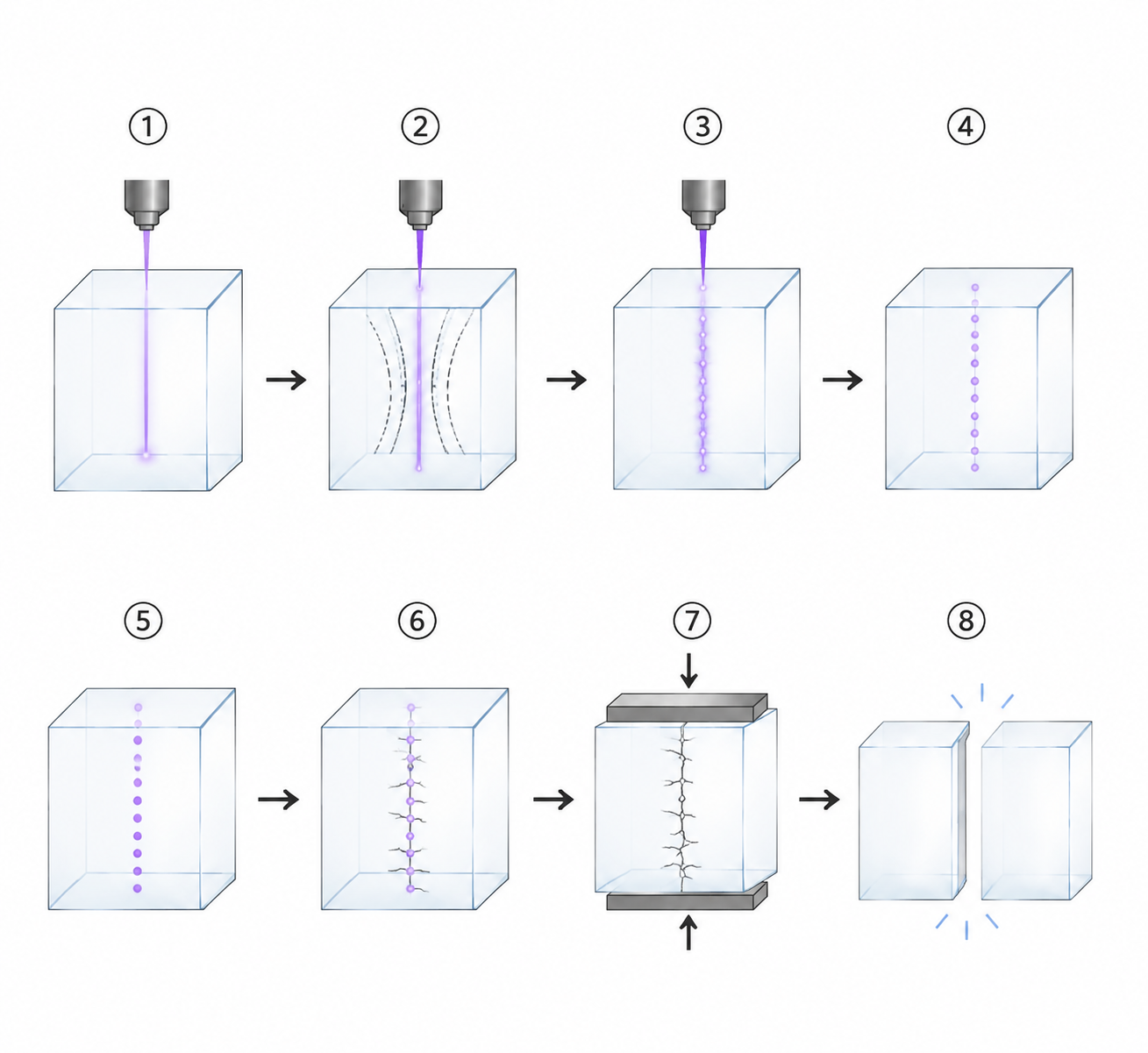
3. Separation Techniques
After the filament modification, the glass must be separated. Several methods can be applied:
| Method | Description | Best For |
|---|---|---|
| Mechanical stress | Applying bending or tensile force along the cut line | Thin glass (<0.5 mm); simple straight cuts. |
| Thermal stress | Localised heating (e.g., with a CO₂ laser) along the filament path | Thick glass; curved cuts. |
| Vacuum or air pressure | Applying differential pressure across the glass | Large‑area panels; automated separation. |
| Ultrasonic vibration | High‑frequency vibration to propagate the fracture | Fragile glass; delicate components. |
Note: In many production environments, the separation step is integrated into the same system, using a secondary laser or mechanical fixture to ensure clean, consistent breakage.
4. Key Advantages of Filamentation Cutting
| Advantage | Explanation |
|---|---|
| High cutting speed | The laser moves at up to 1 m/s, making filamentation significantly faster than surface ablation for most applications. |
| Excellent edge quality | No chipping, no micro‑cracks, no subsurface damage—the edges are clean and smooth. |
| High edge strength | The absence of thermal damage and mechanical stress means the edge strength is nearly equal to the bulk glass. |
| Minimal post‑processing | No grinding, polishing, or cleaning required—reduces cost and cycle time. |
| No taper | The internal modification is vertical, resulting in straight, parallel sidewalls. |
| Low material loss | The kerf is extremely narrow (<10 µm), minimising material waste—critical for expensive glass substrates. |
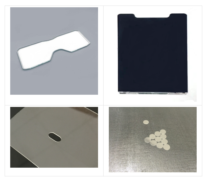
| Suitable for irregular shapes | Any shape—straight lines, curves, inner contours, outer contours—can be programmed. |
| Low debris generation | No significant debris or contamination—the surface remains clean. |
| Supports thick glass | Can cut glass up to several millimetres thick in a single pass. |
5. Application Scenarios
5.1. Thin Glass (<200 µm)
| Application | Why Filamentation Excels |
|---|---|
| UTG (Ultra‑Thin Glass) | Non‑contact, no mechanical stress, preserves the integrity of 30–100 µm glass. |
| Display substrates | Clean edges for OLED and LCD panels; no debris that could contaminate the surface. |
| Flexible electronics | Supports high‑speed cutting of thin, fragile substrates. |
| Sensor windows | Precision cutting of small‑form‑factor optical components. |
5.2. Medium Glass (200 µm – 1 mm)
| Application | Why Filamentation Excels |
|---|---|
| Cover glass | Smartphone, automotive, and consumer electronics covers—high‑speed cutting of strengthened glass. |
| Optical components | Lenses, filters, prisms—precise shaping without surface damage. |
| Semiconductor glass substrates | Wafer‑level packaging; interposer glass cutting. |
| Microfluidic chips | Complex channel and contour cutting. |
5.3. Thick Glass (>1 mm)
| Application | Why Filamentation Excels |
|---|---|
| Industrial sight glass | Observation windows for high‑temperature applications—thick glass cutting with clean edges. |
| Laboratory glassware | Custom beakers, flasks, and reaction vessels—precision cutting of thick borosilicate. |
| Optical windows | Large‑diameter, thick glass for optical systems. |
| Architectural glass | Decorative and functional glass components—irregular shapes, high‑speed processing. |
5.4. Irregular Shapes and Complex Contours
One of the greatest advantages of filamentation cutting is the ability to process any shape:
| Shape Type | Example Applications |
|---|---|
| Straight lines | Panel singulation; rectangular displays. |
| Curved contours | Smartwatch faces; curved display covers. |
| Inner contours | Camera holes, speaker cutouts, sensor windows. |
| Circular shapes | Optical windows; lens blanks. |
| Complex geometries | Microfluidic channels; custom glass components. |
Key benefit: Unlike mechanical cutting, which is limited by tool geometry, filamentation cutting is software‑defined. Any shape that can be programmed in CAD can be cut, with no tooling changes or setup delays.
6. Chanxan Integrated Solution – IR Picosecond Cutting with CO₂ Laser Splitting
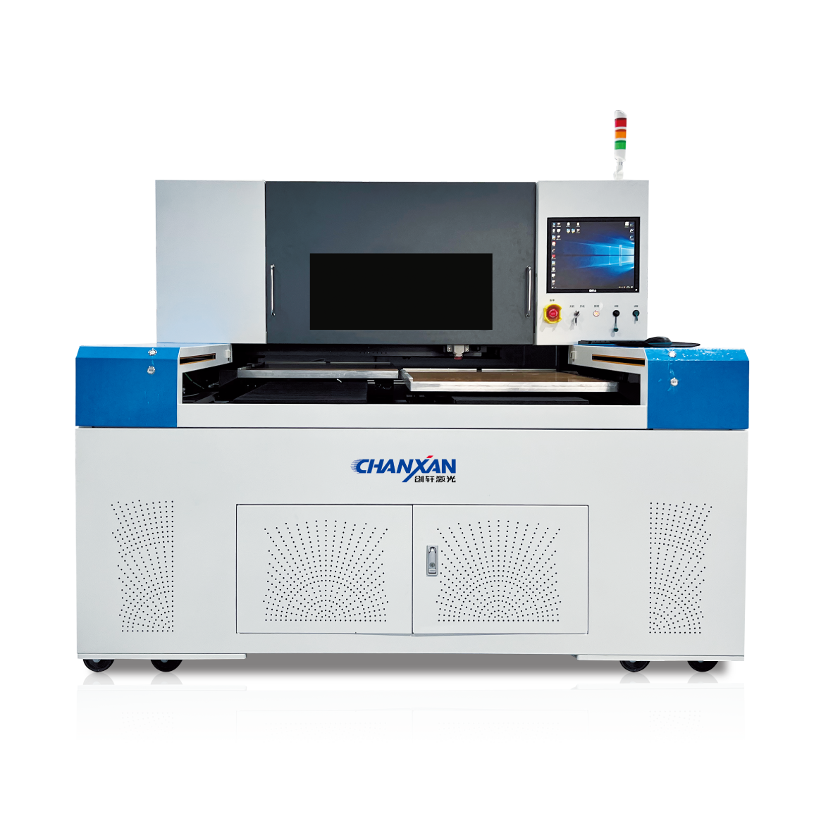
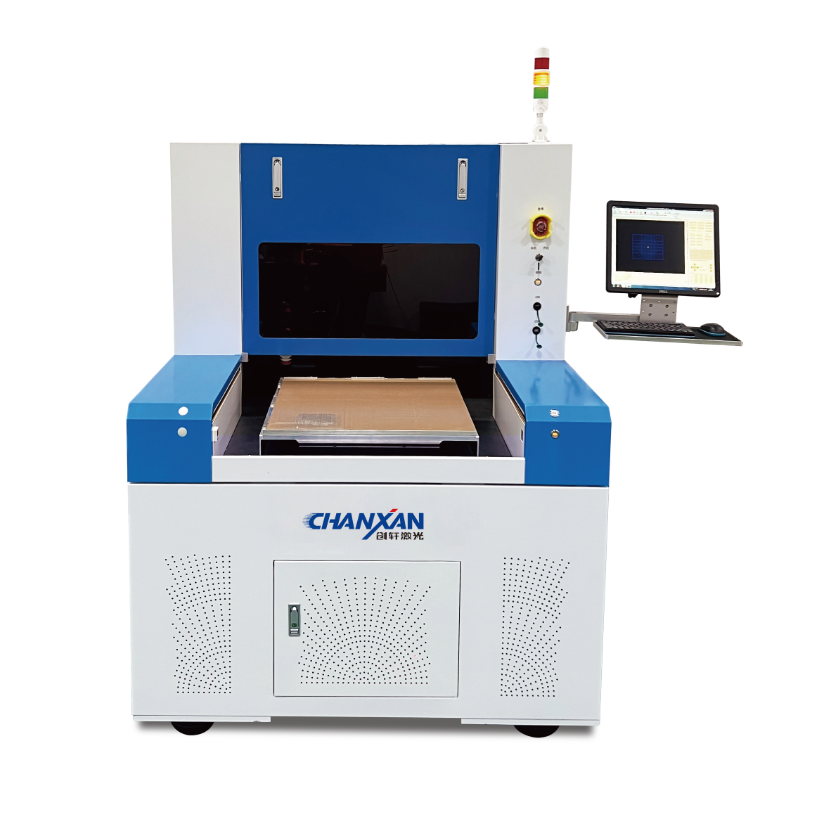
For manufacturers seeking an industrially viable, high‑throughput glass cutting solution, Chanxan offers a uniquely integrated system: the Single/Dual‑Station Picosecond Glass Laser Cutting and Splitting Machine.
The system leverages the physical strengths of different laser wavelengths in a complementary manner: an infrared picosecond (IR ps) laser performs high‑speed internal modification and contour definition, while a CO₂ laser executes controlled thermal splitting along the modified path. This synergistic approach delivers superior quality, speed, and yield across a wide range of glass types and thicknesses.
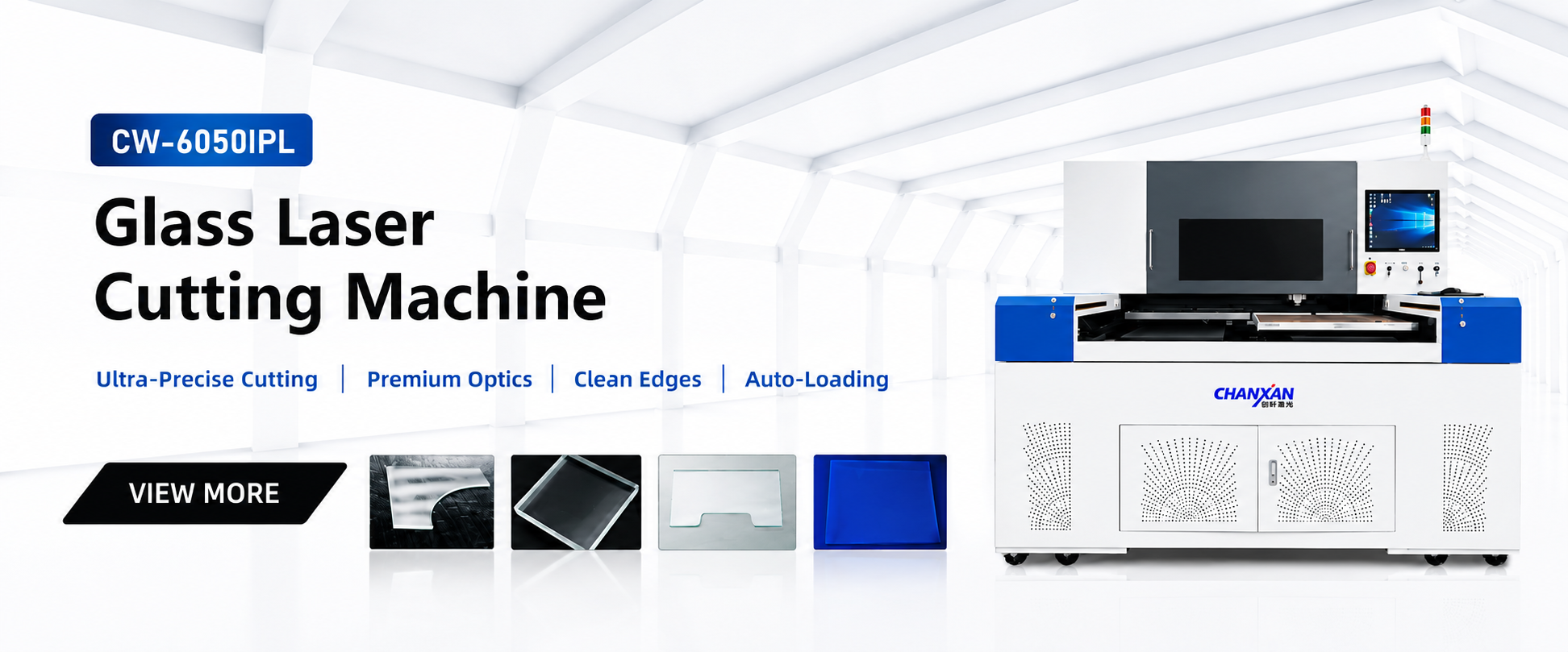
The system integrates filamentation‑based modification with thermal stress‑induced separation:
High‑Speed IR Picosecond Modification: A 70W IR picosecond laser is used for the modification step, efficiently generating a uniform, controllable filamentation layer that defines the precise cutting path.
Precision CO₂ Laser Splitting: After the IR ps laser defines the modification path, a 150W CO₂ laser scans rapidly to generate precise, localised thermal stress guiding the glass to separate cleanly.
Synergistic Performance Benefits:
Minimal Edge Chipping: Chipping is consistently ≤20µm.
Zero Taper Cutting: Edges are completely taper‑free with near‑perpendicular sidewalls.
Low Thermal Impact: Minimises the heat‑affected zone (HAZ) to preserve mechanical strength.
Exceptional Material Compatibility: Proven on optical glass, BK7, borosilicate, aluminosilicate, OLED/LED panels, fused silica, UTG, sapphire, and more up to 3 mm thickness.
Key Specifications and Industrial Design
| Feature | Specification / Benefit |
|---|---|
| Laser Sources | Cutting (modification): 70W IR Picosecond Laser; Splitting: 150W CO₂ Laser |
| Processing Precision | Positioning Accuracy: ±3 µm; Overall Accuracy: ±15 µm; Chipping: ≤20 µm; Taper: None |
| Processing Capability | Thickness: ≤ 3 mm; Min. Hole Diameter: 0.2 – 1.5 mm; Working Area: Single‑station ≤500×500 mm; Dual‑station ≤600×900 mm |
| Motion System | High‑rigidity marble (granite) base with multi‑axis motion (6‑axis on dual‑station system), ensuring micron‑level repeatability. |
| Software Control | Chanxan self‑developed software with direct DXF/DWG import, parameter binding, and an expert process database. |