

Key Words: Silicon Wafer Dicing PCB Depaneling Glass Cutting
Home > News > Industry News
【Description】:
UV vs IR Laser for Precision Glass Cutting – A Complete Comparison
Understanding why UV and IR lasers behave differently when cutting glass requires a brief look at the physics of light‑matter interaction.
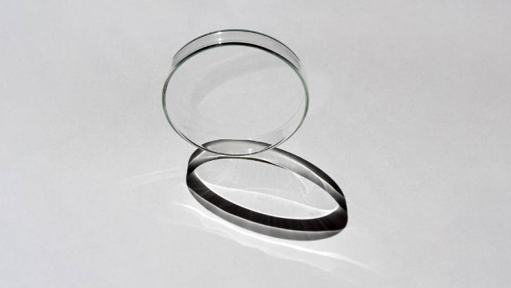
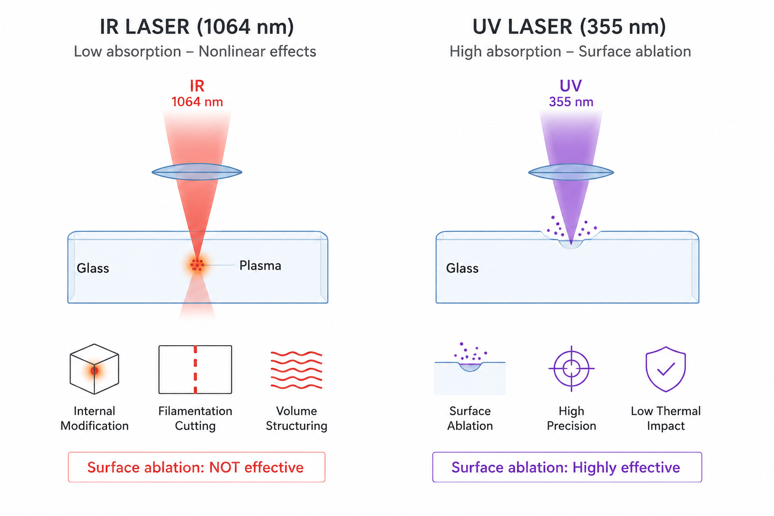
IR lasers (1064 nm) emit light with relatively low photon energy. Most glasses are transparent to IR wavelengths—the beam passes through the material with very little absorption. This is why IR lasers cannot be used for surface ablation of glass in the same way they are used for metals.
However, when an IR laser is focused to a very small spot with extremely high peak power—as is the case with picosecond pulses—the intensity at the focal point becomes high enough to trigger nonlinear absorption. At this point, the glass absorbs the IR energy, creating a localised plasma that modifies the material.
IR lasers are internal modification tools. They work by creating changes inside the glass volume, not by removing material from the surface. This makes them ideal for filamentation cutting and internal structuring, but they cannot cut glass through surface ablation alone.
UV lasers (355 nm) have high photon energy. The wavelength is absorbed efficiently by most glasses at the surface, enabling direct material removal through ablation. The shorter wavelength also allows tighter focusing, which contributes to higher precision.
The photochemical mechanism: UV photons have enough energy to break molecular bonds directly—a photochemical process, not purely thermal. This results in efficient material removal with minimal thermal impact, especially when combined with picosecond pulse durations.
UV lasers are surface tools. They remove material directly from the surface, enabling precise shaping, cutting, and structuring with excellent edge quality.
| Aspect | IR Laser (1064 nm) | UV Laser (355 nm) |
|---|---|---|
| Absorption in glass | Low – passes through | High – surface absorption |
| Primary mechanism | Nonlinear (filamentation) | Surface ablation / cold ablation |
| Where it works | Inside the glass volume | On the glass surface |
| Best application | Thick glass, internal structuring | Thin to medium glass, surface cutting |
IR laser cutting for glass relies on the principle of filamentation. The laser is focused inside the glass, and the high peak power at the focus creates a continuous filament of modified material. This filament extends through the thickness of the glass, following the path of the beam. The glass is then separated along this modified path using a secondary step.
Kerf width: Extremely narrow—the filament is typically only a few microns in diameter.
Edge quality: Excellent—separation follows the internal modification, producing smooth edges.
Taper: Minimal—the filament is vertical through the glass thickness.
Heat‑affected zone: Minimal—the modification is localised to the filament.
Throughput: High—the modification step is fast, and the CO₂ splitting step is rapid.
The glass does not separate on its own—requires a secondary separation step (mechanical, thermal, or chemical).
The process is sensitive to glass composition and internal stress—some glasses filamentate more readily than others.
The filament path must be precisely controlled—focus position is critical.
Thick glass cutting (up to several millimetres)
Curved and irregular profiles
Internal structuring and 3D modification
Applications where a very narrow kerf is valuable
UV laser cutting for glass uses direct ablation. The laser is focused on the glass surface, and the energy is absorbed in a shallow layer. The material melts and vaporises, and the beam is scanned across the surface to create the cut. When combined with picosecond pulse durations, the process becomes cold ablation—material removal with negligible thermal impact.
Kerf width: 20–50 microns—narrower than mechanical methods.
Edge quality: Excellent—smooth, with no chipping and no micro‑cracks (with ps).
Taper: Some taper is possible; can be controlled with multi‑pass cutting.
Heat‑affected zone: Negligible with picosecond pulses (<2 µm).
Throughput: High—fast processing with 30W+ power.
Thick glass (>3 mm) requires many passes—throughput decreases.
Thermal component with nanosecond pulses can create micro‑cracks—picosecond is preferred for critical applications.
Ultra‑thin glass (UTG) for foldable displays
Chemically strengthened cover glass
OLED and LCD panel glass
Optical glass and precision components
Applications requiring edge roughness <0.5 µm
| Aspect | IR Laser (1064 nm) | UV Laser (355 nm) |
|---|---|---|
| Cutting mechanism | Internal modification + separation | Direct ablation / cold ablation |
| Kerf width | <10 µm | 15–50 µm |
| Edge roughness | Excellent | Excellent (Ra <0.5 µm with ps) |
| Micro‑cracks | None (when properly tuned) | None (with ps) |
| Heat‑affected zone | Minimal (internal) | <2 µm (with ps) |
| Thickness range | >1 mm (optimum) | 0.03–3 mm |
| Throughput | High (modification + splitting) | High (direct cutting) |
| Secondary separation | Required (mechanical/CO₂/chemical) | Not required |
| Material sensitivity | Glass composition dependent | Compatible with most glasses |
Recommendation: UV picosecond laser
Why: UTG laser cutting is extremely thin (20–100 µm) and cannot tolerate mechanical contact. UV ps laser cutting delivers crack‑free edges that preserve the glass strength required for >200,000 fold cycles.
Recommendation: UV picosecond laser
Why: The compressive surface layer must be preserved—any thermal or mechanical stress will cause shattering. UV ps cold ablation removes material without affecting the strengthened layer.
Recommendation: UV picosecond laser
Why: Display glass cutting requires particle‑free cutting and smooth edges for hermetic sealing. UV ps laser cutting with nitrogen assist ensures clean, contamination‑free processing.
Recommendation: IR picosecond + CO₂ splitting (hybrid)
Why: UV ablation becomes too slow for thick glass. IR filamentation enables fast internal modification, and CO₂ splitting provides rapid separation with excellent edge quality.
Recommendation: UV picosecond laser
Why: Optical applications require edge roughness below 0.5 µm and zero micro‑cracks. UV ps laser cutting delivers these specifications without the need for post‑processing.
Recommendation: IR picosecond + CO₂ splitting (hybrid)
Why: The filamentation mechanism follows any programmed path, making it ideal for curves and complex shapes in thick glass.
Chanxan Laser provides both UV picosecond and IR picosecond laser systems, enabling manufacturers to select the optimal technology for their specific glass cutting requirements rather than compromising with a one‑size‑fits‑all approach.
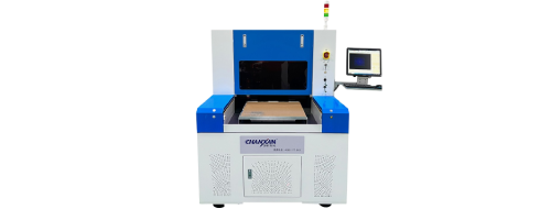
For applications demanding the highest edge quality—UTG for foldable displays, chemically strengthened cover glass, OLED panels, and optical components—the CW-6050PZ UV Picosecond Laser System delivers cold ablation with zero micro‑cracks, edge roughness below 0.5 µm, and ±2 µm repeatability. Its 355 nm wavelength ensures efficient absorption in glass, while the <10 ps pulse duration eliminates thermal damage.
For thick glass, curved profiles, and high‑volume production, the CW‑6050IPL IR Picosecond + CO₂ Splitting System combines fast internal modification with rapid thermal separation. This hybrid approach delivers zero taper, minimal chipping (≤20 µm), and high throughput for display glass, automotive panels, and other demanding applications.
Both systems are built on granite platforms with linear motor drives, feature integrated nitrogen assist and vacuum extraction for clean processing, and are supported by Chanxan's global service network. With expertise across both UV and IR technologies, Chanxan offers manufacturers a single partner for precision glass cutting—regardless of the material thickness, shape complexity, or edge quality required.
| Free solution





