Key Words: Silicon Wafer Dicing PCB Depaneling Glass Cutting
Home > News > Industry News
【Description】:
A comprehensive guide to laser filamentation glass cutting technology, covering its physical principles, two-step modification and separation process, key advantages over conventional ablation, and industrial applications.
Laser filamentation has emerged as one of the most significant advances in precision glass cutting over the past decade. Unlike conventional laser ablation—which removes material from the surface layer by layer—filamentation cutting works from the inside out. The laser is focused deep within the glass, creating a continuous modified path that guides a controlled fracture, enabling clean separation with minimal material loss and exceptional edge quality.
This approach addresses several limitations of traditional glass cutting methods. Mechanical cutting introduces chipping and micro‑cracks. CO₂ laser cutting creates a heat‑affected zone that weakens the glass. Even UV ablation, while highly precise, can be slow for thick materials.
Filamentation cutting offers a compelling alternative: high speed, narrow kerf width, minimal taper, and excellent edge quality across a broad range of glass thicknesses—from ultra‑thin glass (UTG) to thick panels several millimetres deep.
Laser filamentation is a phenomenon that occurs when an ultrafast laser beam—typically picosecond or femtosecond—propagates through a transparent medium such as glass. The beam maintains a narrow, high‑intensity core over an extended distance, creating a permanent modification path within the material.
The physical principle: The filamentation process involves a dynamic balance between two competing effects:
When these two effects reach equilibrium, the beam can propagate through the glass over long distances—millimetres to centimetres—without significant divergence. This stable filament leaves behind a trail of modified glass: a region where the molecular structure has been altered, making it more susceptible to controlled fracture.
The filament is not a physical hole. It is a region of modified material that is structurally weaker than the surrounding glass. It becomes the guide path for subsequent separation.
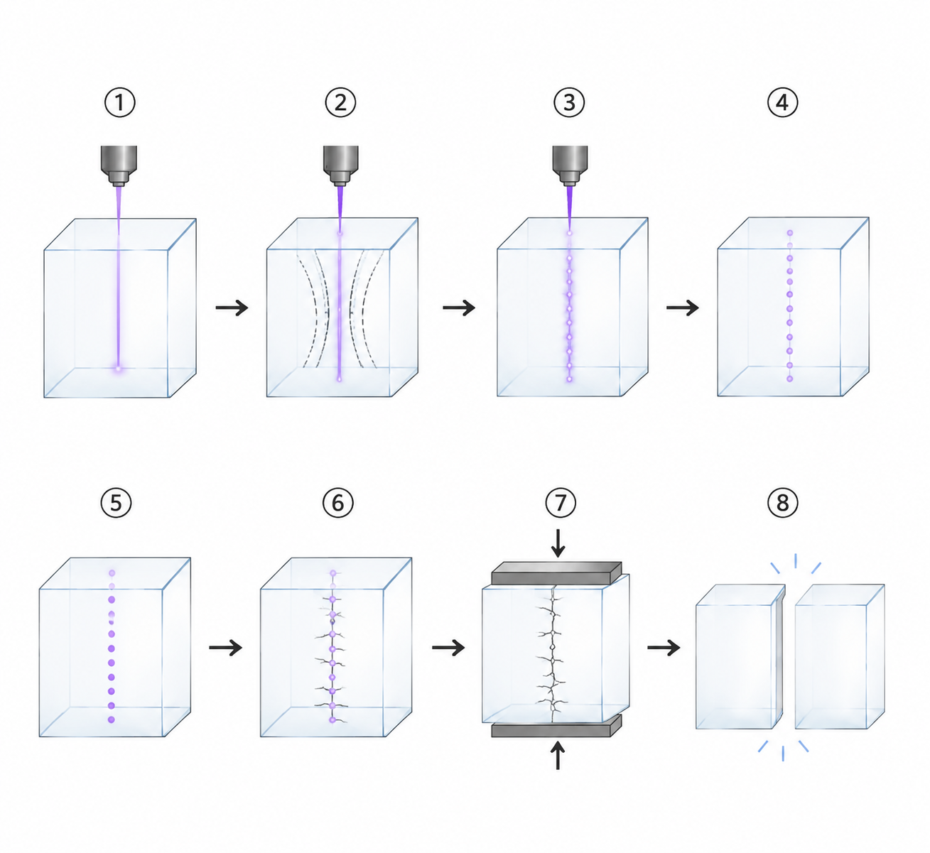
Filamentation cutting is typically a two‑step process:
The modification step: The laser is focused inside the glass—not on the surface. The precise focus position depends on the glass thickness and the desired filament length. Multiple filaments are placed with controlled spacing (typically 5–20 µm apart) to create a continuous modified plane.
The separation step: After the modification, the glass can be separated by:
Mechanical stress: Bending or tensile force along the cut line—effective for thin glass and straight cuts.
Thermal stress: A CO₂ laser scans along the modified path, generating localised thermal stress that separates the glass.
Chemical etching: The modified region etches faster than unmodified glass—a technique used in some specialised applications.
The combination of ultrafast laser modification and CO₂ laser splitting is the most common industrial implementation, offering the speed of internal modification with the efficiency of thermal separation.
Filamentation cutting differs from other laser glass cutting methods in several fundamental ways:
The most important difference: Filamentation cutting does not remove material in the traditional sense. It modifies the internal structure of the glass, creating a controlled fracture path. This means the kerf width is determined by the filament diameter—not by the laser spot size—resulting in extremely narrow cuts and minimal material waste.
While filamentation cutting offers many advantages, it is not without limitations:
Requires a separation step: Unlike direct ablation, filamentation does not immediately separate the glass—a secondary step is required. However, in production environments, this step is integrated into the same system using a CO₂ laser splitter.
Focus position is critical: The filament must be positioned accurately within the glass thickness. Any deviation can affect cut quality and separation.
Not suitable for all glass compositions: Some specialty glasses may not filamentate consistently due to their internal structure or stress distribution.
Throughput for very thin glass: For UTG (<100 µm), pure UV ablation may be faster because the filament length is longer than the material thickness.
Edge quality may require optimisation: While filamentation produces smooth edges, optimising parameters for specific materials and thicknesses requires careful tuning.
The transition from laboratory‑scale research to industrial‑scale production requires more than a high‑performance laser source. A complete processing system must also deliver precise beam delivery, stable motion control, accurate focusing, efficient debris management, and robust process software. Each of these elements affects the final machining quality, and their integration determines whether a process can be reliably repeated across production runs.
This is where the concept of integrated processing systems becomes relevant. These systems combine all necessary components—laser source, beam delivery optics, motion platform, vision alignment, gas management, and process software—into a unified platform designed for consistent, repeatable operation. They enable manufacturers to move from process development to production with reduced risk and faster time‑to‑market.
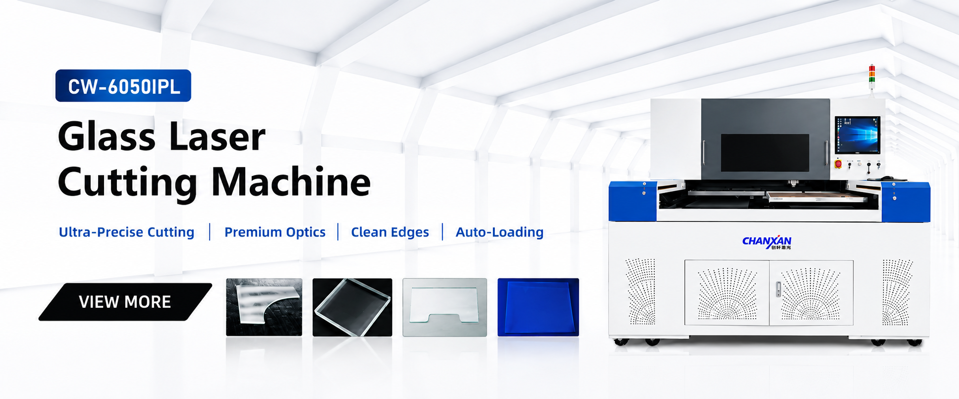
Chanxan Laser offers integrated laser systems that combine IR picosecond laser modification with CO₂ laser splitting, delivering the speed and quality that glass manufacturers require. The CW‑6050IPL Picosecond Glass Laser Cutting and Splitting Machine is purpose‑built for high‑volume filamentation cutting of display glass, automotive panels, and optical components.
Contact Chanxan Laser today to get a customized quote or schedule a sample processing test with our technical experts.
Contact to Get a Quote| Free solution
Previous: Micron‑Scale Glass Laser Ablation – How Ultrafast Lasers Enable Precision Glass Laser Cutting
Next: UV vs IR Laser for Precision Glass Cutting – A Complete Comparison