Key Words: Silicon Wafer Dicing PCB Depaneling Glass Cutting
Home > News > Company News
【Description】:
A field-proven diagnostic guide for identifying and resolving X/Y axis motion issues on galvo-scanner-based laser equipment, including drive status checks, mechanical transmission inspection, and limit switch testing.
In laser processing, the smooth and accurate movement of the X/Y motion stage is fundamental to achieving consistent quality. Any irregularity in axis motion—stuttering, abnormal travel, or complete failure—can ruin parts, reduce throughput, and lead to costly downtime.
This guide provides a systematic, field-proven diagnostic procedure for the most common motion-related faults encountered on galvo-scanner-based laser platforms. By following these steps in order, operators can quickly isolate the root cause—whether electrical, mechanical, or sensor-related—and restore normal operation without unnecessary component replacement.
The X or Y axis does not move smoothly, exhibits jerky or hesitant motion, makes unusual noises, or fails to move at all. In some cases, the axis may move in one direction but not the other, or it may drift from its intended position.
Based on extensive service history, these symptoms typically originate from one of three categories:
Drive connection issues: Faulty drivers, loose or broken wiring, or motor encoder problems.
Mechanical transmission wear/contamination: Dirty, loose, or misaligned pulleys, belts, or gears.
Limit switch malfunction: Defective sensor, incorrect sensing gap, or wiring break.
Perform each step sequentially. Only proceed to the next step after the current checkpoint has been thoroughly checked and ruled out.
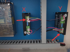
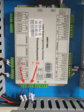
The drive module for each axis has a built-in status indicator LED. This is the quickest way to determine if the issue lies in the electrical drive chain.
| Indicator State | Diagnosis | Action Required |
|---|---|---|
| Solid Green | Drive is powered and operating normally. | Proceed to Step 2. |
| Solid Red | Drive or motor fault detected (overcurrent, overvoltage, short circuit, or encoder error). | Immediately power off the system. Inspect all drive connections, including power input, motor cables, and encoder feedback lines. Look for loose terminals, damaged insulation, or signs of burning. If wiring is intact, swap the drive with a known-good unit (if available) or replace the motor. |
* Note: A red light often appears after a sudden power fluctuation, or when cables are accidentally tugged during routine cleaning. Always ensure cable strain relief is properly secured and connectors are fully seated.
Mechanical transmission components are exposed to dust, debris, and gradual wear—especially in laser applications where polymer ablation generates fine particles that can settle on belts and pulleys.
Visual Inspection: Examine pulleys, timing belts, and gear racks for signs of missing teeth, cracks, excessive wear, or misalignment (belts that track to one side).
Tension Check: The belt should have moderate tension – not so loose that it slips under acceleration (causing lost steps and position drift), and not so tight that it places excessive load on the motor (leading to overheating and premature drive failure). Rule of thumb: The belt should deflect about 5–10 mm under moderate finger pressure at the midpoint.
Cleaning: Use a soft brush or lint-free cloth to remove accumulated dust and debris from all transmission surfaces. For stubborn residues, isopropyl alcohol can be used. Avoid lubricants that attract dust.
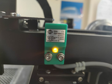
Limit switches define the safe travel boundaries for each axis. A faulty switch can cause the axis to overshoot its end-stop, fail to complete the homing routine, or stop prematurely.
Test Procedure:
Manually jog the axis to bring the metal sensing plate near the limit switch.
Place a small iron or steel plate directly on the sensing face of the limit switch.
Observe the indicator light on the switch body.
| Observation | Diagnosis | Action Required |
|---|---|---|
| Light does NOT turn on | Wiring break, defective switch, or faulty cable inside the drag chain. | Replace the limit switch. Temporarily swap the cable with another axis or use a multimeter to check continuity. |
| Light turns ON | Switch electronics are functional. Verify mechanical gap. | Adjust the height of the metal sensing plate on the slider so that the gap between the plate and switch face is approximately 1 mm. |
* The sensing gap of ~1 mm is essential. Too large = no trigger; too small = physical collision damage. Perform a homing cycle after adjustment to confirm consistency.
Use this checklist to record your diagnostic results during inspection:
| Step | Checkpoint | Status (✔ OK / ✘ Fail) |
|---|---|---|
| 1 | Drive indicator light – Green (normal) / Red (fault) | |
| 2 | Pulleys, belts, and gears – clean, properly tensioned, and free of wear | |
| 3 | Limit switch – indicator responds to metal plate | |
| 4 | Limit switch – sensing gap adjusted to ~1 mm |
Weekly: Wipe down belts and pulleys with a dry cloth; visually check for debris accumulation.
Monthly: Verify belt tension and adjust if needed; test limit switch response with a metal plate.
Quarterly: Inspect drive cables and connectors for signs of wear or oxidation; clean the interior of the electrical cabinet to prevent dust-related overheating.
If the X/Y axis motion problem persists after completing all the above steps, the root cause may lie deeper—in the motion controller, software parameter corruption, worn linear guides, or other complex factors. At Chanxan Laser, we recognize that unplanned downtime directly affects your production targets and profitability.
Rapid Multi-Channel Response: Our technical support team provides initial feedback within 2 hours and dispatches on-site engineers within 24–48 hours for critical stoppages.
Extensive Spare Parts Inventory: We maintain strategically stocked genuine Chanxan components (drives, motors, limit switches, belts) for immediate shipping.
Expert Technical Guidance: Factory-trained engineers guide you through advanced diagnostics, controller parameter tuning, and remote software adjustments.
At Chanxan Laser, we are committed to keeping your production running smoothly. Your success is our priority.
| Free solution
Previous: Client Case Study: Anti‑Glare Glass Cover Processing with 30W UV Picosecond Laser
Next: Client Case Studies: Selective Laser Ablation of Multilayer Composite Film