Key Words: Silicon Wafer Dicing PCB Depaneling Glass Cutting
Home > News > Company News
【Description】:
A field-proven 6-step troubleshooting guide to diagnose and resolve laser firing issues, covering interlock checks, optical path alignment, PSU testing, and parameter configuration.
In laser processing, the most alarming production stop is when the laser simply does not fire. The machine powers on, the motion stage moves, but no beam emerges. This guide provides a structured, field‑proven diagnostic routine to quickly isolate the root cause.
Modern laser systems are protected by a series of interlocks that prevent firing unless all critical subsystems are ready. The most common external interlock is the water chiller—if the chiller is off or the coolant flow is insufficient, the laser power supply will not enable emission. Similarly, the emergency stop and door safety switches can cut the enable signal. Always check these first—many “no fire” calls are resolved by simply turning on the chiller or resetting an E‑stop.
The laser gain medium (whether solid‑state crystal or fiber) generates significant heat during operation. Without active cooling, the internal temperature rises rapidly, risking permanent damage. The chiller interlock is a mandatory safety feature.
Confirm that the chiller’s main power switch is ON and that its display panel shows an active temperature reading (typically 20–25°C).
Listen for the sound of circulating water and check the flow indicator (if fitted).
Ensure the coolant level is within the recommended range—low level can trigger a flow alarm.
If the chiller is off, the laser control panel may display a “Chiller Fault” or simply refuse to fire. Restart the chiller, wait for it to reach the set temperature, then attempt to fire again. If the chiller is running but the laser still does not fire, proceed to the next step.
The laser beam travels from the resonator through a series of turning mirrors and finally to the focusing head (or scanner). Any misalignment—caused by vibration during transportation, thermal drift, or accidental bumping—can deflect the beam so that it never reaches the exit aperture. The laser may still be generating internal light, but it never reaches the workpiece.
Visually inspect all mirror mounts in the beam delivery path. Ensure they are firmly secured and have not shifted.
Look for signs of burning or discolouration on mirror holders, which can indicate that the beam is striking the mount edge rather than the mirror centre.
If your system has a visible pilot laser (red aiming beam), use it as a tracer. The red beam should follow the same path as the processing beam. If the red beam exits the nozzle but the IR/UV beam does not, the alignment is off.
For systems with a removable output coupler or window, check that no dust or debris is blocking the aperture.
Note: Optical alignment is a precision task. If you suspect misalignment but are not trained to perform realignment, contact your service provider. For many systems, a simple adjustment of the last turning mirror can restore output.
This step distinguishes between a laser‑source problem and a control‑signal problem. The control panel usually has a dedicated “TEST” or “PULSE” button that sends a direct fire command to the power supply, bypassing the main processing software.
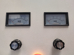
Turn the laser power adjustment knob (if present) fully clockwise to its maximum setting—this ensures the command is not set to zero.
Press the “TEST” button on the control panel (not the software).
Observe the ammeter (current meter) on the power supply or control rack. A reading (e.g., several amperes) indicates that the power supply is receiving the command and is delivering current to the laser tube.
Simultaneously, look into the laser output port (with appropriate safety eyewear) or use a beam‑viewing card to check for a visible flash—some UV lasers emit a faint blue glow, while IR lasers may be invisible but can be detected with a thermal card.
Ammeter shows current, but no beam output → Likely an optical alignment issue (Step 2) or a defective laser tube that cannot convert current into light.
Ammeter shows no current, and no flash → The control signal is not reaching the power supply. Proceed to Step 4.
The power supply converts mains voltage to the specific current and voltage required by the laser tube. If the power supply is not powered, its internal fuse is blown, or its cooling fan has failed, it cannot generate the high voltage needed for laser emission.
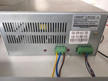
Locate the laser power supply unit (usually a separate box or rack module).
Check that its main power switch is ON.
Inspect the status indicator LEDs:
Power LED: Should be illuminated (green or blue).
Fault LED: Should be OFF.
Listen for the internal cooling fan. If the fan is not spinning, the power supply may have an internal thermal or power failure.
If the unit has a digital display, note any error codes.
The power supply may be receiving input power, but its internal circuit breaker may have tripped. In that case, cycle the main power switch OFF, wait 10 seconds, then ON again. If the fault persists, the supply may need servicing.
In software‑controlled systems, the laser firing is gated by the processing file. If the power setting in the file is set to 0% or below the minimum threshold required to trigger the laser, the system may not emit—even though the hardware is fully functional. Some lasers also require a minimum frequency or pulse width to start oscillation.
Open the current processing job in your laser control software.
Check the power (or duty cycle) parameter. If it is set to 0%, change it to a safe test value—typically 20% of full power.
Also verify that the frequency (repetition rate) is above the laser’s minimum (e.g., >10 kHz for many solid‑state lasers).
Save the file, reload it, and attempt to fire again (either via software or the TEST button with the file active).
This is the definitive test to determine whether the power supply and laser tube are functional independent of the control system. By triggering the power supply directly, you bypass all external signals—including the chiller interlock, emergency stop, and software commands.
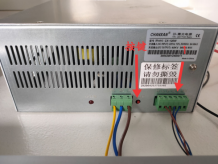
Disconnect the green terminal block (or the designated control signal plug) from the power supply—this removes all external enable signals.
Locate the “TEST” button physically on the power supply unit itself (not the control panel).
Press and hold this button for a short moment (1–2 seconds).
Observe whether the laser tube emits a flash (or the beam card shows output).
If the laser fires during this direct test: The power supply and laser tube are good. The problem lies in the control signal path—wiring, connectors, software, or interlock chain.
If the laser still does not fire: The power supply or the laser tube itself is faulty. The power supply may not be generating the required high voltage, or the tube may have degraded (e.g., gas leakage, crystal damage).
After completing each step, record the results. This table is invaluable when escalating to technical support.
| Step | Test Performed | Result (Pass / Fail / Notes) |
|---|---|---|
| 1 | Chiller power and coolant flow | |
| 2 | Optical path alignment | |
| 3 | Panel TEST – ammeter reading | |
| 3 | Panel TEST – laser flash | |
| 4 | Power supply indicator & fan | |
| 5 | Parameter reset to 20% power | |
| 6 | PSU direct TEST (green terminal removed) |
If you have completed all diagnostic steps and the laser still does not fire, the fault may lie in a deeper component—such as the controller board, internal wiring, or the laser resonator itself. At Chanxan Laser, we understand that every minute of downtime affects your production targets.
Please contact our technical support team with your completed test results, along with:
Machine model number
Laser tube model and wattage
Photos or videos of the control panel and power supply during testing
*Our engineering team typically responds within 24 hours.
| Free solution
Previous: Fume Extraction Troubleshooting: Sealing & Cleaning for Laser Systems
Next: Client Case Study: Anti‑Glare Glass Cover Processing with 30W UV Picosecond Laser