Key Words: Silicon Wafer Dicing PCB Depaneling Glass Cutting
Home > News > Industry News
【Description】:
An in-depth guide on LTCC green tape lamination parameters, via formation methods comparing mechanical punching vs UV laser drilling, picosecond vs nanosecond laser sources, and via filling integration.
Low-Temperature Co-fired Ceramic (LTCC) technology has become a cornerstone of modern microelectronics packaging, enabling the integration of complex multilayer circuits into compact, high-performance substrates. At the heart of this manufacturing process lie two critical, interrelated steps: lamination—the bonding of individual green tape layers into a monolithic stack—and via formation—the creation of vertical interconnections that will later carry electrical signals between layers. Understanding these processes is essential for achieving high yield, reliable electrical performance, and mechanical integrity in the final LTCC substrate.
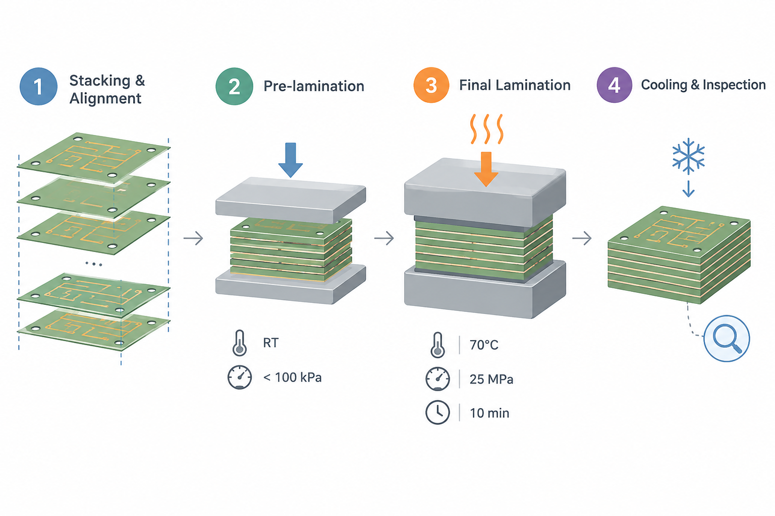
Lamination is the process by which individual ceramic green tape layers—each already printed with conductor patterns and featuring vias—are aligned, stacked, and bonded together under controlled temperature and pressure. The goal is to create a unified, void-free multilayer structure that will survive the subsequent co-firing step without delamination, warpage, or registration errors.
The lamination workflow typically proceeds as follows:
Stacking and alignment: Tooling holes or optical alignment marks precisely align individual green tape layers. Layer-to-layer registration is critical—misalignment of even a few micrometres can cause via mismatch and electrical open circuits.
Pre-lamination (tacking): The stacked layers are lightly pressed at low pressure (typically below 100 kPa) and room temperature to hold them together temporarily. This step allows inspection and repositioning if needed.
Final lamination (isostatic or uniaxial pressing): The stack is subjected to elevated temperature and pressure for a specified duration. Typical parameters reported in the literature include temperatures of 60–80°C, pressures of 21–30 MPa, and hold times of 10–16 minutes. One widely cited reference recommends 70°C, 10 minutes, and 25 MPa for optimal interlayer bonding with minimal substrate deformation.
Cooling and inspection: The laminated block is cooled under controlled conditions before proceeding to via filling and firing.
The quality of the laminated stack depends on three primary parameters, which must be carefully optimised for each specific LTCC material system:
Once the green tape layers have been laminated, the next critical step is the creation of vias—small holes through the tape that will be filled with conductive paste to form vertical electrical connections between layers. In advanced LTCC designs, via diameters can range from 50 μm to over 200 μm, depending on the application and layer thickness.
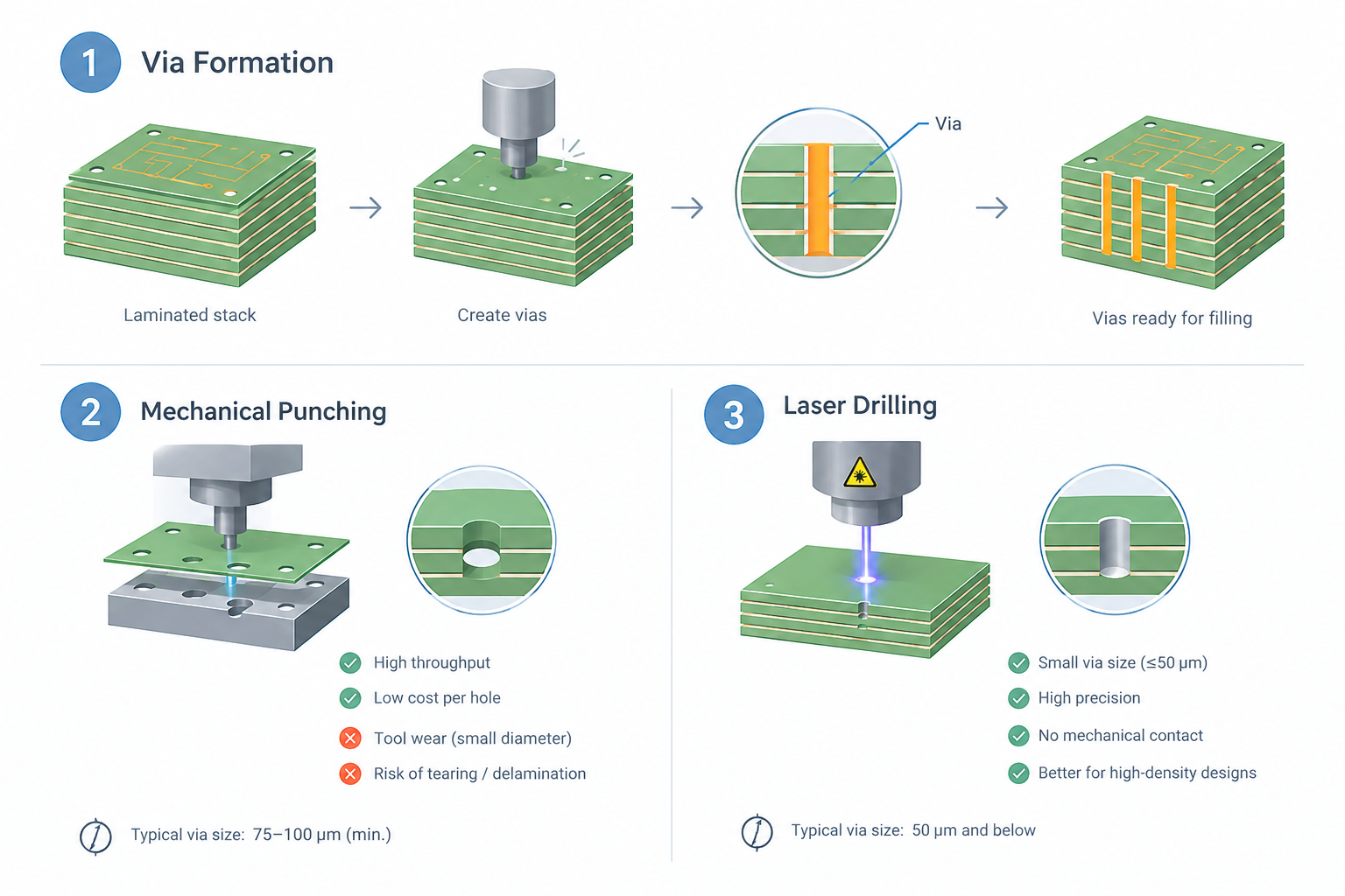
Vias in LTCC green tape can be created by two primary methods: mechanical punching and laser drilling. Each has distinct advantages and limitations.
Mechanical punching uses a punch-and-die set to stamp holes through the tape. It remains the standard technology for many production lines due to its high throughput and low cost per hole. However, mechanical punching faces significant limitations as via diameters shrink:
Tool wear becomes a major cost factor with small-diameter punches.
Minimum practical via size is typically around 75–100 μm.
Punching can cause edge tearing or delamination in thin or fragile green tapes.
Changing via sizes requires physical tool changes, reducing flexibility.
Laser drilling uses a focused laser beam to ablate material, creating vias with diameters down to 50 μm or below. For LTCC green tape processing, laser drilling has become increasingly dominant as circuit densities increase and via sizes decrease.
For green tape (typically 50–200 μm thick), the UV laser (355 nm wavelength) is strongly preferred. The organic binders and plasticisers present in the green tape absorb UV energy efficiently, enabling clean material removal with minimal thermal damage to the surrounding ceramic.
UV laser drilling offers several distinct advantages for LTCC green tape:
High precision: Via diameters down to 50 μm can be achieved with excellent positional accuracy.
Flexibility: Different via sizes and shapes can be programmed without tool changes.
Minimal mechanical stress: No physical contact means no edge tearing or delamination.
High aspect ratio capability: Vias can be drilled through multilayer stacks after lamination.
The choice between nanosecond and picosecond laser sources for LTCC drilling involves trade-offs between throughput, quality, and cost:
| Parameter | Nanosecond UV Laser | Picosecond UV Laser |
|---|---|---|
| Pulse duration | ~10–50 ns | ~10 ps |
| Heat-affected zone (HAZ) | 5–20 μm (visible) | <5 μm (minimal) |
| Throughput | Higher (more material removal per pulse) | Lower (less material per pulse) |
| Equipment cost | Lower | Significantly higher |
| Edge quality | Good; some micro-cracking possible | Excellent; "cold ablation" regime |
For high-volume production where throughput is paramount, nanosecond UV lasers remain a cost-effective choice. For applications requiring the finest features and minimal thermal impact—such as via diameters below 50 μm or drilling through delicate multilayer stacks—picosecond lasers offer superior quality. Studies have shown that for certain LTCC compositions, the heat-affected zone hardness after nanosecond processing can be reduced by 72–77%, which may actually benefit subsequent mechanical processing steps.
A known challenge in laser drilling of LTCC green tape is the hole explosion phenomenon—the violent expulsion of material from the via during drilling, which can create irregular hole shapes and debris deposition. Research has shown that this effect can be suppressed by adding carbon black to the green tape formulation. Studies report that with 10 wt% carbon black content and 3 W laser power, the hole explosion rate can be reduced to as low as 0.8%. This highlights the importance of close collaboration between material suppliers and process engineers.
Once vias are formed, they must be filled with conductive paste—typically silver, gold, or copper formulations—to create the electrical interconnection. Via filling is commonly performed by screen printing, which forces conductive paste into the via holes and onto the surface pads in a single operation.
The quality of via filling is critical to the final electrical performance of the LTCC substrate. Incomplete filling can lead to open circuits or high resistance; overfilling can cause shorts between adjacent features. The filled vias must be thoroughly dried before the next layer is laminated, and the entire assembly is then co-fired to densify the ceramic and sinter the conductive paste into a solid metallic interconnection.
While this article has presented lamination and via formation as sequential steps, the reality in LTCC manufacturing is more intertwined:
Vias can be formed before lamination (individual tape layers are drilled or punched, then stacked and laminated) or after lamination (the entire multilayer stack is drilled in one operation). Post-lamination drilling offers superior via alignment but requires laser technology that can handle the increased thickness.
Via filling is typically performed after lamination to prevent paste contamination between layers.
The lamination process itself can affect via quality—excessive pressure or temperature can distort via shapes.
For high-density designs with via diameters below 75 μm, the combination of post-lamination UV laser drilling followed by screen-printed via filling has become the industry standard.
The successful fabrication of multilayer LTCC structures depends on mastering both lamination and via formation. As via diameters continue to shrink and layer counts increase, the role of precision laser micromachining in LTCC processing has become indispensable.
Chanxan Laser offers dedicated UV nanosecond and picosecond laser systems engineered specifically for high-quality LTCC green tape via drilling. Our solutions address the key challenges faced by LTCC manufacturers:
✓ High-precision via drilling: Achieve clean, taper-controlled vias down to 50 μm diameter with positional accuracy of ±20 μm, ensuring reliable interlayer connections.
✓ Minimal thermal impact: Advanced pulse control limits the heat-affected zone to below 20 μm (nanosecond) or 5 μm (picosecond), preserving the integrity of the green tape and preventing delamination or edge cracking.
✓ Flexible processing: Support for both pre-lamination (single-layer) and post-lamination (multilayer stack) via drilling, adapting to your production workflow.
✓ Process optimisation: Our application engineers work with customers to define optimal parameters—pulse energy, repetition rate, scanning speed, and focal position—for each specific LTCC tape formulation, ensuring maximum throughput with zero defect rates.
✓ High-throughput automation: Integrated motion platforms with ±1 μm repeatability and scanning speeds up to 3000 mm/s enable cost-effective volume production.
Whether you are manufacturing 5G RF modules, automotive radar substrates, or high-reliability medical packaging, Chanxan Laser provides the technology and support to meet your LTCC via drilling requirements with precision, consistency, and efficiency.
Contact Chanxan Laser today to discuss your LTCC green tape processing needs or request a complimentary sample drilling trial on your material.
Contact Chanxan Laser Today →| Free solution
Previous: Laser Drilling vs. Mechanical Punching for LTCC Green Tapes: A Head‑to‑Head Comparison
Next: LTCC Green Tape: A Complete Guide to Low-Temperature Co-Fired Ceramic Tape