Key Words: Silicon Wafer Dicing PCB Depaneling Glass Cutting
Home > News > Industry News
【Description】:
Learn how LTCC green tape works as an LTCC substrate material, including composition, electrical and mechanical properties, co-firing, applications, standards and material selection.
LTCC green tape is an unfired, flexible ceramic tape used to manufacture multilayer electronic substrates, packages, interconnects and embedded passive components. The term LTCC means Low Temperature Co-Fired Ceramic. Unlike a fired ceramic substrate, green tape is a process-ready intermediate material. It can be punched, laser-cut, printed with conductor pastes, stacked, laminated and then fired to form a dense ceramic structure with internal electrical functions.
The technology is important because it combines ceramic stability with multilayer integration. A well-designed LTCC system can support low-loss RF transmission, buried conductors, embedded resistors and capacitors, three-dimensional routing, cavities and hermetic or near-hermetic packaging. Its comparatively low firing temperature also enables co-firing with selected low-resistance conductor systems, including silver, gold and, for compatible material systems, copper.
The most important point for engineers is that LTCC green tape is a complete material system, not merely a ceramic sheet. Its powder chemistry, organic vehicle, tape thickness, lamination behaviour, firing shrinkage, conductor compatibility and final dielectric properties must be designed together. A tape that performs well electrically may be difficult to laminate. A tape with excellent mechanical strength may have a thermal expansion coefficient that does not match the die or housing. Product selection should therefore begin with the final package architecture and manufacturing process, rather than with dielectric constant alone.
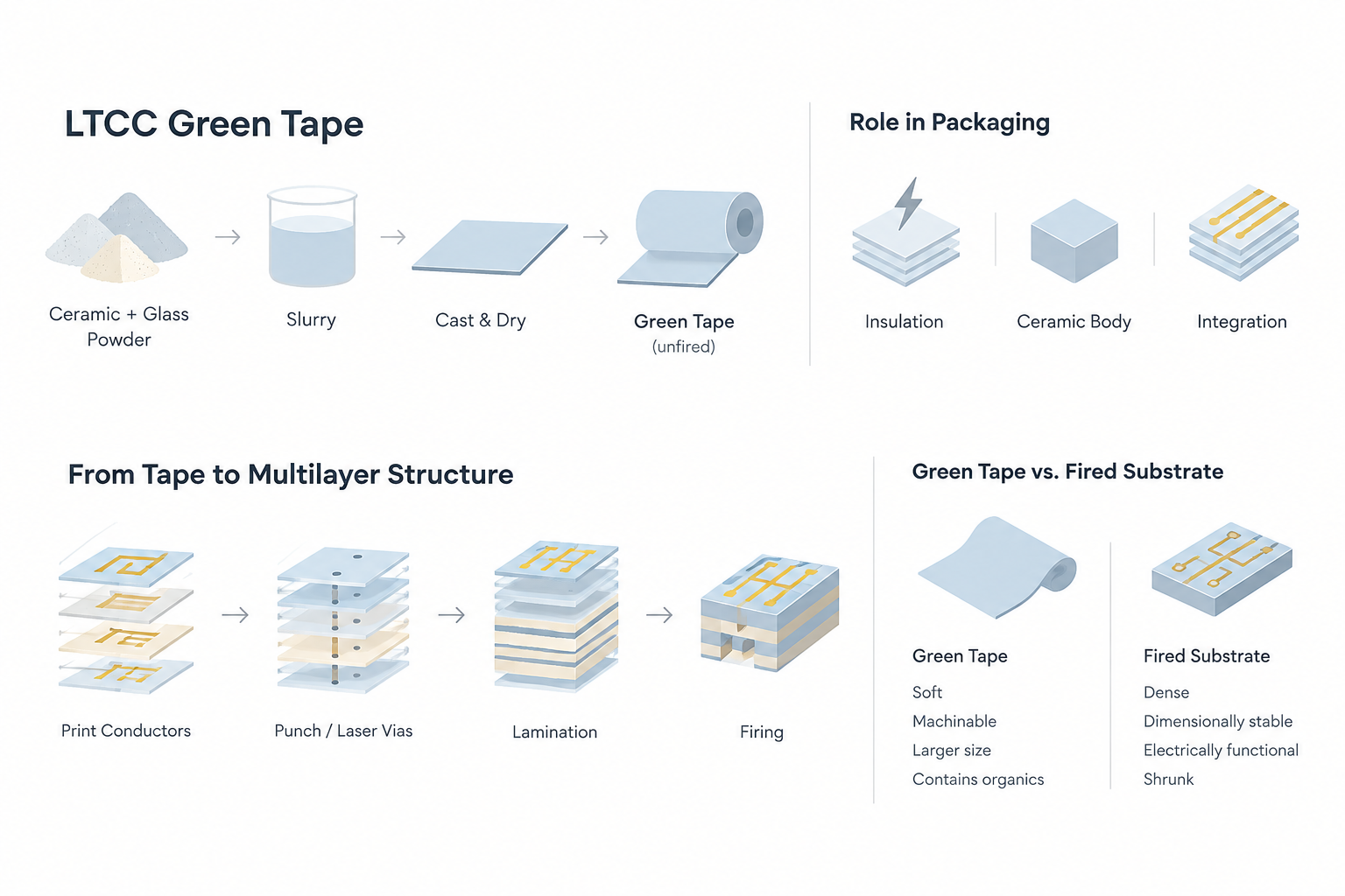
LTCC green tape is produced by dispersing ceramic and glass-forming powders in an organic slurry, casting that slurry into a controlled-thickness sheet, drying it and removing the carrier film. The word “green” refers to the unfired state. It does not describe the tape’s colour, although some commercial products may appear white, cream or green depending on the formulation and pigment.
In microelectronics packaging, the tape serves three functions at the same time. First, it provides electrical insulation between conductor layers. Second, it becomes the mechanically stable ceramic body after firing. Third, it provides a manufacturable platform for integrating conductors, vias, cavities and passive functions into a compact multilayer structure.
A conventional ceramic package may require separate substrate, interconnect, cavity and component-attachment steps. LTCC can combine several of these functions in one co-fired architecture. Conductive patterns are printed onto individual tape layers, interlayer connections are formed through punched or laser-drilled vias, and the layers are registered and laminated before firing. During the firing cycle, the organic components are removed and the inorganic portion densifies into a ceramic composite.
The result is an LTCC ceramic substrate or package with features that are difficult to obtain economically in a single-layer ceramic process. These features include buried transmission lines, multilayer antennas, integrated filters, embedded resistors, cavities for sensors, thermal vias and compact feedthroughs. Research literature describes LTCC as a technology for three-dimensional multilayer electronic substrates, RF circuits and MEMS systems, particularly where miniaturization and operation in demanding environments are required.
The distinction between green tape and fired substrate is essential when interpreting a datasheet. Green tape is soft, machinable and dimensionally larger than the final fired part. It contains polymers and solvents that are later removed. Its strength, flexibility and dielectric measurements are not equivalent to those of the fired ceramic.
The fired LTCC substrate is dense, dimensionally stable and electrically functional, but it has already undergone significant shrinkage. The final properties depend on firing temperature, dwell time, heating rate, atmosphere, laminate thickness, conductor loading and the interaction between adjacent materials. A tape datasheet should therefore identify whether each value applies to the unfired tape, the fired dielectric, a single-layer test coupon or a complete multilayer assembly.
| Term | Meaning | Typical engineering concern |
|---|---|---|
| Green tape | Unfired ceramic composite sheet | Flexibility, handling, punching, printing and lamination |
| LTCC laminate | Stacked and laminated tape layers before firing | Registration, trapped air, layer bonding and internal stress |
| Fired LTCC dielectric | Densified ceramic after binder removal and sintering | Dk, tan δ, CTE, strength, porosity and shrinkage |
| LTCC substrate | Finished multilayer ceramic structure with conductors and features | Electrical performance, dimensional tolerance and reliability |
| LTCC package | Substrate combined with cavity, lid, feedthrough or device-attachment features | Hermeticity, thermal path, assembly and qualification |
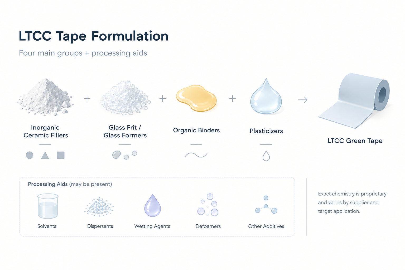
A commercial Low Temperature Co-fired Ceramic tape normally contains four main formulation groups: inorganic ceramic fillers, glass frit or glass-forming constituents, organic binders, and plasticizers. Solvents, dispersants, wetting agents, defoamers and other processing aids may also be present. Exact chemistry is proprietary and varies by supplier and target application.
Ceramic fillers provide part of the fired skeleton and influence dielectric behaviour, thermal expansion, stiffness, shrinkage and crystallization. Alumina is widely used because it offers high hardness, good insulation, useful thermal conductivity and established supply chains. In LTCC systems, however, alumina is often combined with a glass phase rather than used as a conventional high-temperature alumina body.
Other filler families may include quartz, silica, cordierite-related phases, titanate-containing powders, zirconia-containing modifiers or application-specific functional ceramics. A published study of a quartz-based LTCC system reported a composite powder containing a glass phase, quartz as the principal ceramic filler, anatase and small amounts of spinel and alumina. After firing, glass crystallization created additional ceramic phases. This illustrates why the initial powder recipe and final fired microstructure should not be treated as identical.
Fillers affect the dielectric constant in several ways. A low-permittivity filler can reduce the effective Dk of the composite. A higher-permittivity or polarizable filler can raise Dk or introduce frequency dependence. Particle size distribution also matters because it affects packing, viscosity, pore formation and sintering kinetics.
Glass frit is one of the defining ingredients of many LTCC systems. It lowers the temperature at which the inorganic phase softens, wets the ceramic particles and densifies. During firing, the glass may remain partly amorphous, crystallize into one or more phases, or react with fillers and conductor materials.
This glass phase makes LTCC different from high-temperature co-fired alumina. By engineering the glass chemistry, manufacturers can target a peak firing temperature compatible with selected conductor systems. The glass also influences thermal expansion, dielectric loss, mechanical strength, chemical resistance and moisture sensitivity.
Glass chemistry must be controlled carefully. Excessive glass content may increase shrinkage, reduce thermal conductivity or alter long-term stability. An unsuitable glass can react with silver, gold or copper conductors, change the conductor interface or create voids. The glass transition and crystallization behaviour can also make the firing profile sensitive to heating rate and dwell time.
Organic binders hold the inorganic particles together in the unfired tape and provide enough toughness for handling, punching, printing and stacking. Common binder families include polymer systems selected for compatibility with the solvent package and casting process. The binder must provide green strength without making the tape excessively brittle or difficult to remove.
Binder burnout is a critical stage of the co-firing process. If the binder decomposes too quickly, gases can become trapped inside the laminate and cause blisters, delamination or internal voids. If burnout is incomplete, carbonaceous residues can affect insulation resistance, conductor interfaces and final density. Thick or highly laminated structures normally require a slower and better-controlled burnout segment than thin single-layer coupons.
Plasticizers increase flexibility and reduce the glass-transition temperature of the organic system. They help prevent cracking during handling and improve the tape’s ability to conform during lamination. The plasticizer level must be balanced: too little can make the tape brittle, while too much can reduce green strength, increase tack or complicate burnout.
Dispersants, solvents, defoamers and rheology modifiers are used to control slurry stability and tape-casting quality. Poor dispersion can produce agglomerates, pinholes, thickness variation and local dielectric non-uniformity. Entrained air can create defects that become internal voids after firing. For this reason, slurry preparation, filtration, vacuum de-airing, casting speed and drying conditions are part of the material-performance system.
Because formulations differ, a useful way to compare materials is to ask what each ingredient is intended to control rather than to compare undisclosed percentages. The following table summarizes the main design role of each group.
| Formulation group | Main function in green tape | Effect on fired LTCC | Typical risk if poorly controlled |
|---|---|---|---|
| Alumina or other ceramic filler | Provides inorganic body and controls thermal/mechanical behaviour | Strength, CTE, thermal conductivity and part of Dk | Poor packing, high porosity or property variation |
| Glass frit / glass-forming powder | Enables low-temperature densification and phase formation | Sintering temperature, loss, CTE and chemical compatibility | Excess shrinkage, reactions or unstable microstructure |
| Organic binder | Provides green strength and handling integrity | Must be removed cleanly during burnout | Delamination, residue or cracking |
| Plasticizer | Improves flexibility and lamination response | Influences burnout load and dimensional stability | Tack, low green strength or gas generation |
| Solvent and dispersant system | Produces a stable castable slurry | Indirectly affects uniformity and defects | Agglomeration, bubbles, pinholes or thickness variation |
The LTCC manufacturing route is a sequence of tightly linked steps. A defect introduced during tape casting may appear later as a dielectric failure. A registration error during printing may become a via short after stacking. A small burnout problem may become a blister after sintering. Process control must therefore cover the entire chain.
Inorganic powders are weighed, mixed and dispersed with the organic vehicle. The slurry is filtered and de-aired before it is cast onto a carrier film. The casting head, web speed, viscosity, drying temperature and solvent-removal rate determine tape thickness and surface quality.
The target is a uniform sheet without pinholes, agglomerates, bubbles, streaks or excessive residual stress. Tape thickness can range from thin dielectric layers for fine interconnect structures to thicker layers for mechanical support and cavities. Incoming inspection should include thickness mapping, visual inspection, flexibility, surface energy and green tensile or handling behaviour where required.
Vias are formed by mechanical punching, laser drilling or another suitable method. The choice depends on via diameter, layer thickness, throughput and positional accuracy. The holes are then filled with conductive paste or prepared for subsequent conductor printing.
Conductor patterns may include signal traces, ground planes, pads, inductors, capacitors, resistors, antennas and thermal paths. Screen printing is common, but fine-line structures may require specialized processes. Paste rheology, drying and print thickness must be compatible with the green tape and the final co-fire profile.
Printed layers are aligned using tooling holes, registration pins, optical systems or automated stack-and-tack equipment. Layer registration controls via alignment, line width, cavity dimensions and electrical repeatability.
The aligned stack is laminated using uniaxial or isostatic pressure. Temperature, pressure, time and vacuum conditions are selected to achieve interlayer bonding without distorting vias or collapsing cavities. A commercial LTCC design guide describes heated lamination conditions around 70°C and 3,000 psi for a representative process, while noting that the actual parameters must be adjusted to achieve the required result.
Lamination defects include trapped air, incomplete bonding, excessive flow, layer shift and cavity deformation. Cross-sectional microscopy and X-ray inspection are valuable for process development. A laminate that looks acceptable externally may still contain internal voids or registration errors.
The laminate is heated slowly through the temperature range where solvents, binders and plasticizers decompose. This step is often called debinding or organic burnout. The heating rate must allow gases to diffuse out through available paths without creating excessive internal pressure.
Thick laminates, dense conductor patterns and low-permeability surfaces require special attention. The burnout schedule may include one or more holds. In one commercial example, organic burnout was controlled between approximately 200°C and 550°C before the material reached its peak firing temperature. This is a process example rather than a universal recipe.
After burnout, the inorganic layers densify and the glass phase flows or crystallizes. Conductors co-fire during the same thermal cycle. Peak temperature is selected to meet the LTCC chemistry and conductor compatibility requirements. Many LTCC systems fire below 1,000°C; published examples include firing near 900°C, and one commercial system guide specifies a peak around 850°C for selected grades.
The firing profile includes ramp rates, holds, peak temperature, dwell time, cooling rate, setter selection and atmosphere. A smooth, flat setter helps control warpage. Some materials require coated or dedicated setter tiles to avoid sticking or surface reactions. Box furnaces and belt furnaces may be used depending on size, throughput and dimensional-control requirements.
After co-firing, the module may undergo conductor plating, resistor trimming, thick-film post-fire operations, dicing, laser processing, lid attachment, sealing, component assembly and electrical test. The order depends on the product architecture.
Inspection commonly includes dimensional measurement, optical inspection, X-ray or computed tomography, cross-section analysis, continuity and isolation testing, RF characterization, adhesion testing and environmental reliability testing. The acceptance criteria should be defined in the drawing, purchase specification or quality agreement rather than inferred from a general LTCC datasheet.
The dielectric tape and conductor paste must densify in a compatible way. If the conductor restrains the ceramic or shrinks differently, it can cause warpage, cracking, conductor distortion or open circuits. Large-area ground planes and uneven copper or silver distribution can create local stress. Dummy fill or balanced patterning may improve uniformity.
Incomplete burnout can leave residue or cause blistering. Excessively rapid burnout can generate internal pressure. The correct schedule depends on organic loading, part thickness, via fill, laminate density and furnace airflow. Process development should use thermal analysis, witness coupons and destructive cross-sections rather than relying on furnace temperature alone.
Silver, gold and copper require compatible firing atmospheres, glass chemistry and paste systems. Copper generally requires controlled atmosphere processing to prevent oxidation. A conductor that is chemically stable in a single-layer test may behave differently when buried in a multilayer laminate. Designers should use the conductor system recommended for the exact tape grade.
Warpage can result from non-uniform shrinkage, asymmetric layer construction, temperature gradients, setter friction or conductor imbalance. Delamination can originate from poor tape adhesion, contamination, trapped solvent or excessive lamination flow. Symmetric stack design, controlled drying, appropriate lamination and validated furnace loading are important countermeasures.
A small dimensional shift can change the impedance or resonant frequency of a microwave circuit. RF designs should include the statistical variation of fired line width, dielectric thickness, Dk, conductor thickness and shrinkage. Test coupons should be placed near production features, particularly for high-frequency or high-density designs.
Ceramic itself is generally stable, but glass-rich surfaces, residues, pores, plating and package interfaces can respond to moisture and contamination. Surface cleaning, storage humidity, bake conditions and encapsulation may affect insulation resistance and RF performance. The final qualification should reproduce the actual customer assembly and operating environment.
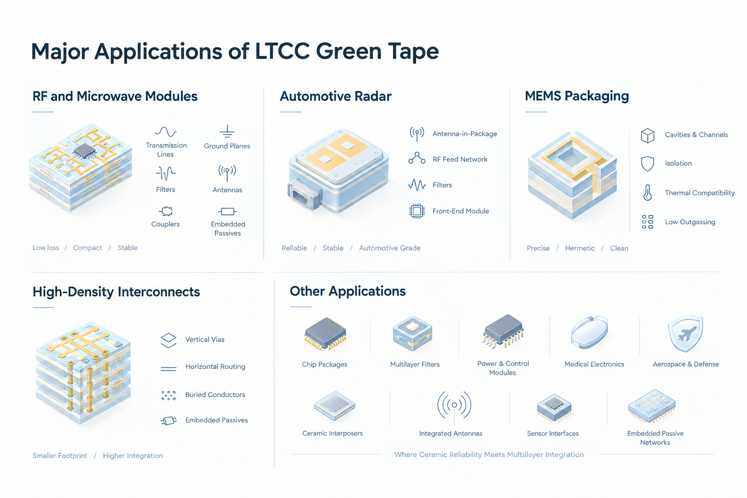
LTCC is widely used in RF modules because it supports multilayer transmission lines, buried ground planes, filters, couplers, antennas, baluns and embedded passives. The low-loss characteristics of selected LTCC grades help reduce transmission loss at high frequencies. Low-temperature processing also supports compact integration of conductor layers and functional elements.
The designer must model the actual fired stackup. Dk and tan δ should be characterized at the operating band, while conductor roughness, via inductance, surface finish and cavity effects should be included in the electromagnetic simulation. LTCC is particularly attractive when the module must be compact, repeatable and stable across temperature.
Automotive radar systems operate in demanding mechanical and thermal environments. LTCC can support antenna-in-package structures, RF feed networks, filters and compact front-end modules. Its ceramic body provides dimensional stability and can be engineered for a useful CTE relationship with semiconductor dies and external materials.
Automotive use places strong demands on traceability, process capability, thermal cycling, vibration, moisture resistance and long-term supply. A material’s laboratory Dk is not enough. Qualification should cover the complete antenna or radar module, including soldering, lid or radome interfaces, board attachment and environmental exposure. Suppliers serving automotive programs may also be expected to operate an automotive quality management system such as IATF 16949, where applicable to the supply chain.
LTCC supports cavities, channels, feedthroughs and multilayer structures that are useful for MEMS packaging. Sensors and actuators may require a controlled cavity, electrical isolation, low outgassing behaviour, thermal compatibility or integration with functional ceramic layers. The tape process allows cavities and access features to be formed before firing, but cavity collapse, contamination and dimensional change must be characterized.
MEMS applications often require tighter control of surface cleanliness, hermeticity, particle generation and stress than a conventional interconnect module. The package design should define whether the cavity must be hermetic, leak-tight under a specific test method or simply protected from the external environment.
LTCC green tape enables vertical interconnection through vias and horizontal routing across multiple layers. This supports compact modules with buried conductors, stacked vias, thermal vias and embedded passive elements. It can reduce package footprint and shorten electrical paths compared with a collection of discrete components.
High-density designs are limited by tape thickness, via diameter, via pitch, conductor resolution, registration tolerance, lamination flow and fired shrinkage. Design rules should be obtained from the manufacturing supplier and confirmed through a representative build. IPC-6018 is associated with qualification and performance requirements for high-frequency microwave boards, but it should not be assumed to cover every LTCC package feature without a project-specific interpretation.
Additional applications include chip packages, multilayer filters, power and control modules, implantable or medical electronics, aerospace and defense electronics, ceramic interposers, integrated antennas, sensor interfaces and embedded passive networks. LTCC is most valuable where the combination of ceramic reliability, multilayer integration and low-temperature conductor compatibility creates a clear system-level advantage.
It contains ceramic and glass-forming powders, but it is not yet a dense ceramic substrate. It is an unfired composite with organic binders and plasticizers. The ceramic properties used in design normally refer to the fired material under specified test conditions.
The term is relative to high-temperature co-fired ceramic systems, which commonly require substantially higher firing temperatures. The lower LTCC window enables compatibility with selected low-resistance conductors and supports multilayer co-firing.
No. “Green” describes the unfired state. The physical colour depends on the composition, pigment and supplier. Fired parts may be white, grey, beige or another colour.
Some LTCC systems are designed for copper co-firing, but copper requires suitable chemistry and atmosphere control. Do not combine a generic tape with copper paste without a validated material and process recommendation.
No. Lower Dk can reduce parasitic capacitance and support certain RF structures, while higher Dk can enable smaller resonators and capacitors. The correct target depends on impedance, frequency, size, bandwidth and thermal requirements.
Use the supplier’s validated shrinkage data for the exact tape grade, thickness, layer construction, conductor pattern and firing process. Confirm compensation with a test vehicle because x-y and z shrinkage may differ and may vary across the panel.
No. LTCC offers multilayer integration and lower-temperature processing, but alumina or aluminium nitride may be preferable for specific thermal, mechanical, cost or high-temperature requirements. Material selection should be application-specific.
LTCC green tape is a manufacturing platform for building compact, multilayer ceramic packages and substrates. Its value comes from the coordinated behaviour of the inorganic powder system, glass chemistry, organic vehicle, conductor paste and co-firing profile. When these elements are matched correctly, LTCC can provide low-loss RF routing, embedded passive components, high-density interconnects, cavities, thermal vias and reliable ceramic packaging in a compact structure.
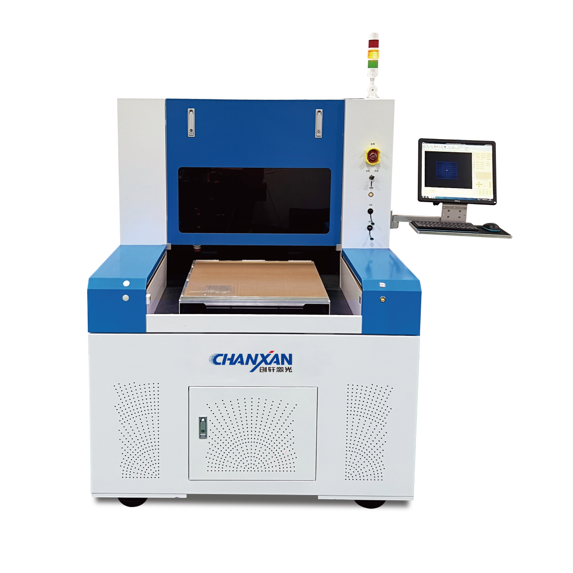
Need a cleaner, more precise way to process LTCC green tape before lamination and co-firing? Chanxan Laser's ultrafast laser platform is designed for high-precision LTCC laser processing, including microvia drilling, through-hole formation, blind-hole processing and fine-feature patterning.
Ultrafast laser pulses can help minimize heat-affected zones and reduce the risk of thermal damage around delicate ceramic features. With optimized beam delivery, pulse control and process parameters, the platform can support consistent hole quality, small feature sizes and high-density interconnect manufacturing across demanding LTCC applications.
Talk to Chanxan Laser's application engineering team about your LTCC laser drilling requirements. Share your tape thickness, target hole diameter, aspect ratio, throughput, positional tolerance and co-firing process so the team can recommend a suitable ultrafast laser platform and arrange a sample-processing evaluation.
Request an LTCC Laser Drilling Consultation
Request an LTCC laser drilling consultation, explore sample processing, or learn more about Chanxan Laser's ultrafast laser platform for precision ceramic manufacturing.
| Free solution
Previous: Lamination and Via Formation: Building Multilayer LTCC Structures
Next: Laser Parameters for Precision Glass Cutting – A Technical Guide to Process Optimisation