1. Introduction: The Fundamental Question in Glass Machining
When engineers first consider manufacturing Through‑Glass Vias (TGVs), the most instinctive question is often: "Can't we just drill these holes mechanically, like we do with PCBs?"
It is a valid question. Mechanical drilling using solid carbide or diamond‑coated tools is a mature, well‑understood technology. For decades, glass drilling machines have been widely used in architectural glass, automotive glazing, and display manufacturing. However, when the application shifts to glass interposers for advanced semiconductor packaging – where via diameters shrink to 30–100 µm, aspect ratios exceed 10:1, and glass thicknesses approach 500 µm – mechanical drilling encounters fundamental physical limitations.
This article provides a side‑by‑side comparison of laser drilling and mechanical drilling for TGV fabrication. We examine hole quality, aspect ratio capability, edge integrity, and cost – and explain why, for advanced packaging, the choice is no longer a debate.
2. Mechanical Drilling for Glass – Capabilities and Limitations
2.1. The Principle
Mechanical drilling uses a rotating tool – typically a solid carbide micro‑drill or a diamond‑coated bit – to physically shear and fracture the glass. The process relies on:
High‑speed rotation (typically 10,000–80,000 RPM).
Controlled feed force to advance the tool.
Coolant/lubricant to reduce friction and flush debris.
2.2. Practical Industrial Capabilities
| Parameter | Typical Capability (Industrial Context) |
|---|---|
| Minimum practical via diameter | >200 µm for robust production; 150 µm possible under highly optimised (but costly) conditions |
| Maximum reliable aspect ratio | ≤4:1 (beyond this, tool breakage and quality degradation become statistically significant) |
| Substrate thickness range | 0.5 mm – 5 mm (but diameters scale proportionally) |
| Tool wear | Significant – glass is highly abrasive, requiring frequent replacement, particularly for small-diameter tools |
| Edge quality | Chipping at entry/exit and subsurface micro‑cracks are inherent to the process |
| Taper | Dependent on tool wear; typically 1–3° in production |
2.3. The Fundamental Failure Mechanisms
Glass is brittle and lacks ductility. Mechanical drilling imposes three types of damage that are unacceptable for TGV applications:
| Failure Mode | Mechanism | Impact on TGV Reliability |
|---|---|---|
| Entry/exit chipping | Tensile stress fractures the glass around the hole perimeter | Compromises surface planarity; prevents fine‑line RDL patterning on the interposer |
| Subsurface micro‑cracks | Mechanical force propagates cracks 50–100 µm beyond the visible hole wall | These are not optically visible but cause catastrophic failure during thermal cycling (reflow, field operation) |
| Progressive tool wear | Diamond grains dull or peel; carbide shanks fracture | Leads to oversized, tapered, or incomplete holes across a production batch |
Critical observation: As via diameter decreases, mechanical drilling becomes exponentially less viable. A 100 µm drill bit is as fragile as a human hair; a 50 µm bit is mechanically impractical for any sustained production run.
3. Laser Drilling for Glass – The Enabling Technology for TGV
Laser drilling, specifically using UV picosecond sources, removes glass by vaporisation and ablation – a non‑contact process that eliminates mechanical stress.
3.1. The Principle
Ultrafast pulses (<10 ps) are focused onto the glass surface.
Nonlinear absorption (multi‑photon ionisation) creates a localised micro‑plasma that ejects material.
The extremely short pulse duration prevents heat diffusion – enabling "cold ablation."
The beam is scanned in trepanning (spiral) patterns to progressively form the via.
3.2. Practical Industrial Capabilities
| Parameter | Typical Capability (UV Picosecond Laser) |
|---|---|
| Minimum via diameter | 30–50 µm (production‑proven) |
| Reliable aspect ratio | 10:1 to 15:1 (industrial); up to 20:1 in specialised R&D |
| Substrate thickness range | 100 µm – 1 mm (with dynamic Z‑focus tracking) |
| Tool wear / consumables | None – no physical contact; 100% process repeatability |
| Edge quality | No chipping; sidewall roughness typically ≤0.5 µm (Ra) |
| Micro‑cracks | Eliminated – cold ablation avoids mechanical stress |
| Throughput | Under typical conditions (e.g., 100 µm diameter, 300 µm thickness): 3,000–7,000 vias/hour |
4. Head‑to‑Head Comparison – Laser vs. Mechanical for Glass Vias
| Parameter | Mechanical Drilling | Laser Drilling (UV Picosecond) | Practical Verdict |
|---|---|---|---|
| Practical diameter range | >200 µm (robust); 150 µm (extreme) | 30–200 µm (flexible) | Laser – covers the entire TGV range; mechanical cannot reach small diameters reliably. |
| Aspect ratio capability | ≤4:1 (production) | 10:1 to 15:1 (production) | Laser – essential for deep, narrow vias in 3D packaging. |
| Edge chipping | Inherent – cannot be eliminated | None | Laser – critical for surface planarity. |
| Subsurface micro‑cracks | Inherent – statistically present | None (with correct parameters) | Laser – eliminates hidden failure modes. |
| Tool wear | High – frequent replacement | None | Laser – reduces consumable costs and downtime. |
| Throughput (small vias, <150 µm) | Not feasible | 3,000–7,000 holes/hour* | Laser – mechanical cannot compete. |
| Throughput (large holes, >500 µm) | Fast – seconds per hole | Slower – requires multiple passes | Mechanical – more efficient for coarse, non‑critical holes. |
| Process flexibility | Fixed tooling; design changes require new bits | Software‑defined; instant adjustments | Laser – ideal for prototyping and mixed‑variety production. |
| Capital equipment cost | Lower entry cost | Higher investment | Mechanical has lower initial cost, but ROI analysis favours laser for high‑volume TGV. |
| Cost per via (high volume) | Increases with tool wear and smaller diameters | Fixed – independent of diameter | Laser – more predictable and often lower for fine‑pitch arrays. |
| Substrate stress | High – mechanical force induces warp | Zero – non‑contact | Laser – eliminates stress‑related warpage. |
| Process cleanliness | Requires coolant; produces abrasive slurry | Dry process; minimal debris (with assist gas) | Laser – cleaner, no liquid waste handling. |
| Industrial adoption for TGV | None – not used in advanced packaging lines | Dominant – industry standard | Laser – mechanical is absent from modern TGV production. |
* Throughput dependent on specific via geometry and glass thickness. Figure represents typical conditions (100 µm diameter, 300 µm thickness) for reference.
5. Where Mechanical Drilling Remains Relevant
To maintain objectivity, mechanical drilling is not obsolete for all glass applications. It retains value in specific, non‑TGV scenarios:
| Application | Why Mechanical Is Preferred |
|---|---|
| Large alignment / tooling holes (>500 µm) | Loose tolerances; high throughput; low cost. |
| Thick glass (>2 mm) with large diameters (>1 mm) | Laser drilling thick glass is slow; mechanical is faster for these coarse features. |
| Non‑critical glass components (e.g., display cover glass) | Quality requirements are far below semiconductor standards. |
| Low‑volume, large‑hole prototypes | Accessible with standard workshop equipment. |
Critical distinction: These are not TGV applications. They do not undergo metallisation, high‑density routing, or stringent thermal cycling tests. For advanced packaging, these exceptions do not apply.
6. Why the Semiconductor Industry Has Chosen Laser for TGV
The advanced packaging industry – driving 5G, automotive radar, AI, and photonics – imposes requirements that mechanical drilling cannot meet:
Density: A single glass interposer may contain tens of thousands of vias in a 20×20 mm area. Mechanical drilling cannot achieve the required pitch (centre‑to‑centre spacing) below 200 µm.
Reliability: One micro‑crack in a single via can cause the entire interposer to fail during thermal cycling (e.g., 1,000 cycles from -55°C to +125°C). Mechanical drilling introduces statistically inevitable micro‑cracks.
Surface integrity: After drilling, the glass surface must remain flat for wafer‑level RDL (redistribution layer) lithography. Mechanical chipping ruins surface planarity.
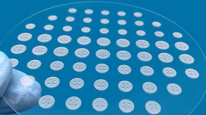
Aspect ratio: 3D stacking requires vias that are deep and narrow. A 500 µm thick interposer with 50 µm vias (10:1 aspect ratio) is typical – mechanical drilling cannot approach this with acceptable yield.
Panel‑scale processing: Glass interposers are moving to large panels (up to 500×500 mm). Mechanical drilling on such large panels requires extensive fixturing and risks panel breakage; laser systems with galvo scanners process the entire panel in a single setup without mechanical stress.
In short: For TGV – a semiconductor packaging technology – laser drilling is the only physically viable method that meets the combination of density, reliability, and substrate integrity.
7. The Evolution of Glass Drilling Equipment
The term glass drilling machine has evolved. Today, it includes both legacy mechanical spindles and advanced laser‑based systems:
| Machine Type | Typical Features | Application Suitability |
|---|---|---|
| Mechanical spindle glass drill | Rotary chuck, coolant delivery, diamond tooling, X‑Y stage | Large holes (>500 µm), thick glass, non‑precision applications. |
| Thermal laser systems (CO₂ / ns IR) | Limited to cutting and scribing; produces significant HAZ | Not suitable for TGV – causes micro‑cracks and thermal damage. |
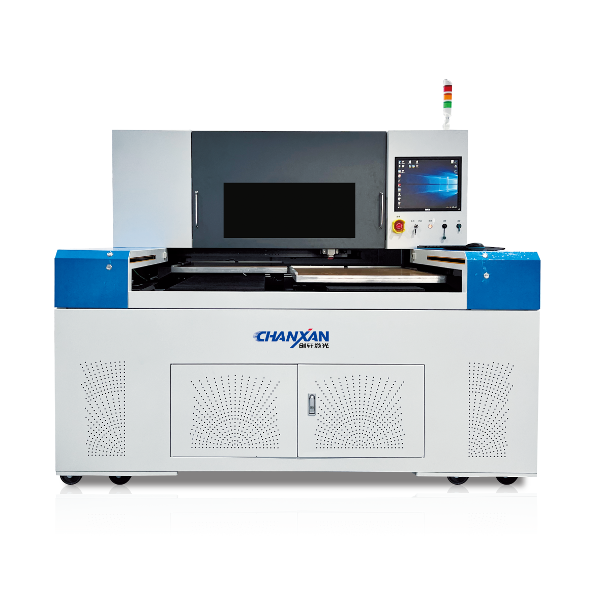
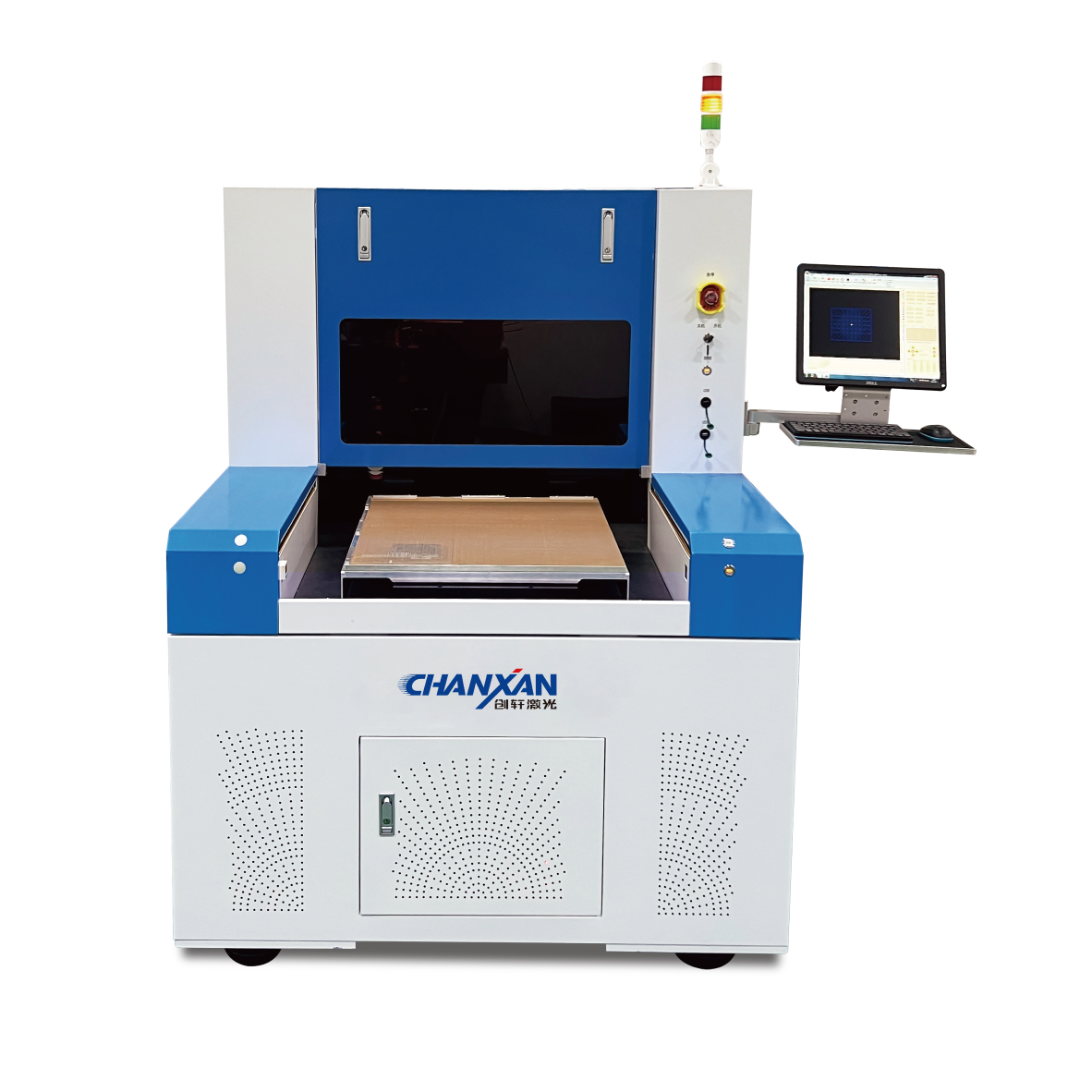
| UV picosecond laser glass drilling system | Galvo scanner, dynamic Z‑axis focus tracking, debris evacuation, trepanning software | Industry standard for TGV – delivers the required quality and throughput. |
The modern solution for glass via drilling is unambiguously the UV picosecond laser system.
8. Practical Process Selection Framework
For engineers evaluating equipment for TGV production, consider this decision matrix:
| Primary Requirement | Recommended Process | Rationale |
|---|---|---|
| Via diameter < 150 µm | Laser | Mechanical cannot achieve this reliably. |
| Aspect ratio > 5:1 | Laser | Mechanical exceeds practical limits. |
| Semiconductor‑grade reliability | Laser | Eliminates micro‑cracks and chipping. |
| Glass thickness 100–500 µm | Laser | Dynamic focus tracking ensures uniform quality. |
| High‑volume production (>100,000 vias) | Laser | Lower cost per via with no tool replacement overhead. |
| Large holes (>500 µm) only | Mechanical | Faster for coarse features; lower capital cost. |
| Non‑critical applications (non-TGV) | Mechanical | Cost‑effective when quality demands are relaxed. |
Conclusion: The Clear Winner for TGV Manufacturing
The comparison between laser drilling and mechanical drilling for Through‑Glass Vias reveals a stark technical and economic reality: laser drilling has displaced mechanical drilling entirely from advanced packaging.
Mechanical drilling remains viable for large‑diameter, low‑precision applications. However, for TGV – the cornerstone of modern glass interposer technology – the combination of required miniaturisation, reliability, throughput, and surface integrity leaves no room for mechanical methods.
The semiconductor industry's unanimous adoption of UV picosecond lasers for TGV production is not arbitrary; it reflects decades of collective experience that mechanical drilling simply cannot meet the standards of advanced 5G, automotive radar, and AI packaging.
Ready to implement laser drilling for your TGV production?
Get Expert Consultation