Key Words: Silicon Wafer Dicing PCB Depaneling Glass Cutting
Home > News > Industry News
【Description】:
Master ultrafast (ps/fs) laser cutting & marking for microscope glass slides. Learn key process parameters for chip-free edges and permanent traceability.
Microscope glass slides are among the most widely used consumables in biological and medical laboratories. For over a century, they have served as the standard substrate for mounting, observing, and preserving tissue samples, cells, and microorganisms. Yet, the demands on this humble substrate have evolved significantly.
Today's diagnostic, research, and automated testing environments require:
Custom-dimension slides for specialised fixtures and automated handling systems.
Ultra-thin slides (<150 µm) for high-resolution microscopy and advanced imaging techniques.
Permanent, machine-readable identification marks for traceability, regulatory compliance, and sample tracking.
High-quality edges free from chips and cracks to ensure reliable handling and bonding.
Traditional mechanical processing of glass—cutting, dicing, scribing—is inherently limited. Glass is hard, brittle, and transparent. Mechanical tools induce micro-cracks, chipping, edge roughness, and subsurface damage that compromise both the structural integrity and the optical clarity of the finished slide.
Ultrafast laser technology—specifically picosecond (ps) and femtosecond (fs) lasers—has emerged as the industry-standard solution for precision glass processing.
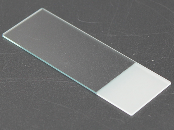
Most standard microscope slides are manufactured from one of three glass types, each with distinct processing characteristics:
| Glass Type | Composition | Key Properties | Typical Application |
|---|---|---|---|
| Soda-lime glass | SiO₂, Na₂O, CaO | Economical, moderate thermal stability, good optical clarity | General-purpose pathology slides, student microscopes |
| Borosilicate glass | SiO₂, B₂O₃, Na₂O | Low thermal expansion, high chemical resistance, excellent optical quality | High-end diagnostics, cell culture slides, micro-arrays |
| Fused silica (quartz) | SiO₂ (99.9+%) | Extremely low thermal expansion, high UV transparency, exceptional durability | UV spectroscopy, fluorescence microscopy, advanced optics |
Common characteristics relevant to processing:
| Property | Impact on Processing |
|---|---|
| High transparency | Limits absorption of longer-wavelength lasers; UV wavelengths (355 nm) are preferred for surface processing. |
| High hardness | Resists scratching but makes mechanical cutting difficult and tool-intensive. |
| High brittleness | Susceptible to chipping, cracking, and edge fracture under mechanical stress. |
| Low thermal conductivity | Heat does not spread quickly; thermal processes (CO₂, ns IR) can cause localised melting and cracking. |
The processing implication: These properties make mechanical cutting, grinding, or scribing of glass slides inherently problematic. The yield loss from edge chips and micro-cracks can be significant—particularly for thin (<0.5 mm) or ultra-thin (<150 µm) slides. Ultrafast laser processing, by contrast, is non-contact, stress-free, and thermally minimal, making it the preferred method for high-quality glass slide fabrication.
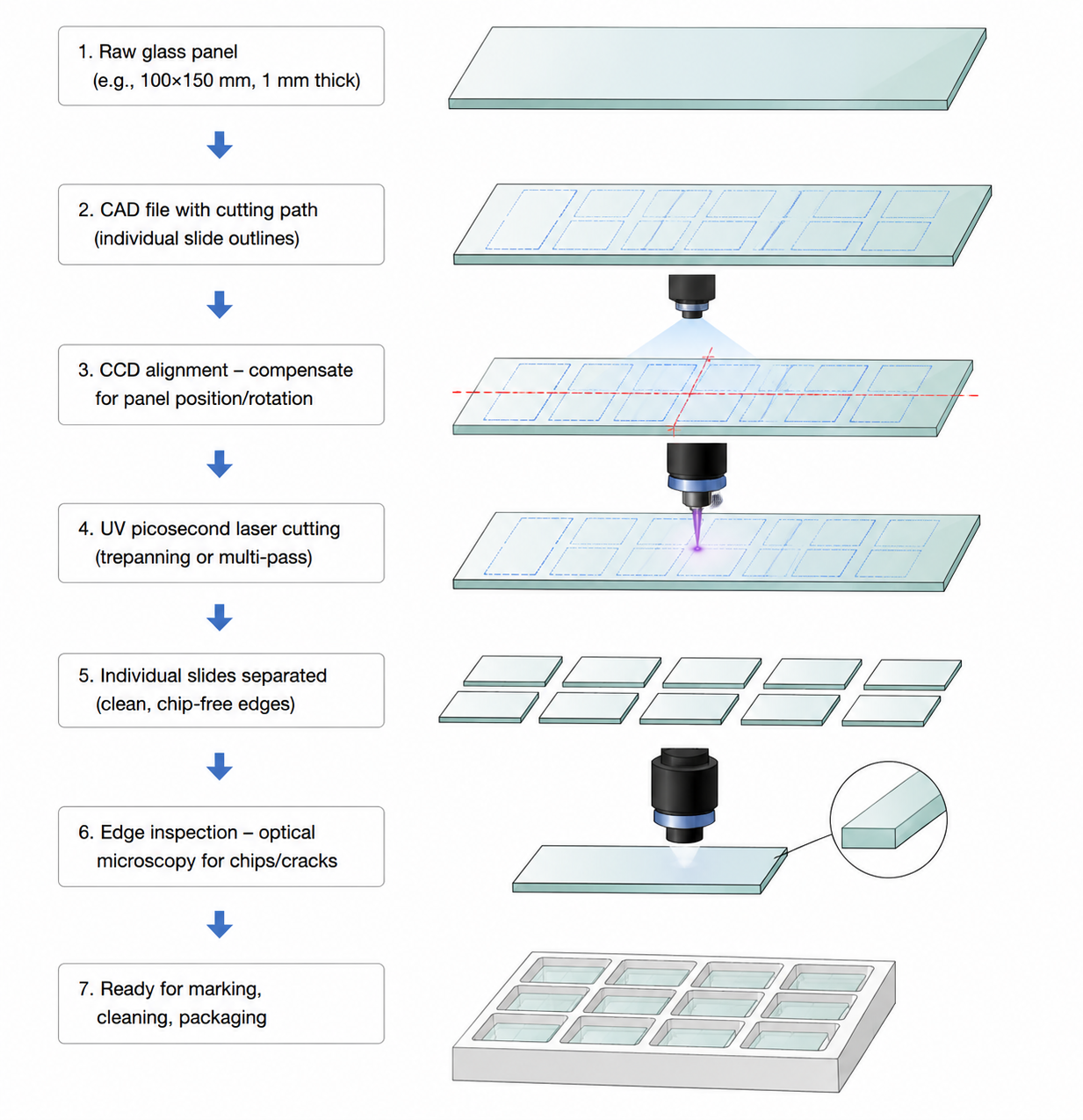
Laser cutting of glass slides uses a focused ultrafast laser beam (picosecond or femtosecond) to ablate (vaporise) the glass along a programmed path. The beam moves relative to the substrate—either by galvanometer scanning or by moving the cutting stage—cutting through the glass with a kerf width typically between 20–50 µm.
Because the pulse duration is extremely short (<10 ps for ps; <500 fs for fs), the energy is deposited before heat can diffuse. This cold ablation regime eliminates:
| Defect Type | Mechanical Cutting | Thermal Laser (CO₂ / ns) | Ultrafast Laser (ps / fs) |
|---|---|---|---|
| Edge chipping | Common – caused by tool impact | Moderate – due to thermal stress | None |
| Micro-cracks | Common – subsurface damage | Possible – due to thermal gradients | None |
| Melt / recast layer | None | Common – material re-deposits | None |
| Heat-affected zone | None (mechanical only) | Significant (>100 µm) | Minimal (<2 µm) |
| Application | Description | Why Laser Cutting Is Preferred |
|---|---|---|
| Custom-size slides | Non-standard dimensions (e.g., 50x25 mm, 100x30 mm) for specialised fixtures or automated analysers | Mechanical dicing causes edge chips; laser provides clean, square edges with <5 µm deviation. |
| Ultra-thin slides | Thickness <150 µm for high-resolution microscopy, TIRF, or super-resolution imaging | Mechanical handling is impossible; laser cutting is non-contact and stress-free. |
| Multi-slide panel singulation | Cutting individual slides from large-format panels (e.g., 100x150 mm) for high-throughput production | High precision and repeatability; no tool wear; no edge chipping. |
| Irregular shapes | Circular, triangular, or custom-contoured slides for specialised sample holders | Laser cutting follows any programmed shape; mechanical cutting is limited to straight lines. |
| Pre-scored slides | Partial-depth scoring for easy manual breaking | Laser scoring produces clean, stress-free score lines with minimal subsurface damage. |
| Parameter | Typical Setting | Practical Consideration |
|---|---|---|
| Laser source | UV picosecond (355 nm) – preferred | UV provides strong surface absorption in all glass types; delivers smooth edges with fewer passes. |
| Pulse energy | 10–50 µJ (adjustable) | Higher energy increases cutting speed but must be controlled to prevent edge chipping. Start low and increment. |
| Repetition rate | 200–500 kHz | Higher frequencies increase throughput; lower frequencies reduce heat accumulation for thick glass. |
| Scanning speed | 100–500 mm/s | Slower speeds improve edge quality; faster speeds increase throughput. Optimise based on glass thickness. |
| Number of passes | 5–20 (depending on thickness) | Each pass removes 5–15 µm of material. More passes = smoother edges but longer cycle time. |
| Focus position | On-surface for top-down cutting; dynamic Z-tracking for thicker glass | Maintains consistent fluence as cutting progresses. |
| Assist gas | Nitrogen or dry air, 1–3 bar | Removes debris; prevents redeposition on the cut edge. Nitrogen also prevents oxidation. |
In medical diagnostics and laboratory workflows, traceability is not optional—it is a regulatory and operational requirement. Microscope slides must be clearly and permanently identified with:
Sample numbers and patient identifiers (anonymised).
Barcodes or 2D data matrix codes for automated scanning.
Date, lot, and batch information for quality control.
Custom text for laboratory-specific coding systems.
Traditional marking methods have significant drawbacks in medical and laboratory environments:
| Method | Drawback |
|---|---|
| Inkjet printing | Ink smears, fades, or dissolves in cleaning solvents; requires drying time. |
| Label stickers | Peel off, become illegible, leave adhesive residue; interfere with optical inspection. |
| Pen / marker writing | Not durable; not machine-readable; variable quality. |
| Etching (chemical) | Hazardous, slow, mask-dependent; not suitable for individual slide marking. |
Laser marking overcomes all these limitations:
| Laser Marking Advantage | Explanation |
|---|---|
| Permanent | Marks survive solvents (ethanol, xylene, acetone), heat (autoclaving), and mechanical abrasion. |
| High contrast | Surface ablation or controlled micro-cracking creates light-scattering marks visible under bright-field and dark-field illumination. |
| Machine-readable | Barcodes and data matrix codes are scannable by standard readers (mobile phones, laboratory scanners). |
| Sub-micron precision | Enables high-density 2D barcodes and micro-text in extremely small surface areas without structural damage. |
Depending on the application requirements, laser marking on microscope slides is generally performed using one of two primary techniques:
| Technique | Mechanism | Key Characteristics | Best Suited For |
|---|---|---|---|
| Surface Micro-Ablation | High-peak-power UV or ultrafast pulses remove a micro-thin top layer (<5 µm depth) to create a frosted, light-scattering mark. | High visual contrast, high scanning speed, tactile finish; requires minimal pulse energy. | 1D/2D barcodes on frosted slide ends, lot numbers, patient IDs. |
| Subsurface Laser Engraving (SSLE) | Focusing ultrafast laser pulses inside the glass substrate to induce localized refractive index changes or micro-disruptions without damaging top or bottom surfaces. | 100% smooth glass surface, zero dust/particulate generation, zero risk of cell/tissue trapping. | High-cleanroom microfluidic slides, specialized optical diagnostic chips. |
| Parameter | Recommended Value | Process Impact |
|---|---|---|
| Laser Wavelength | 355 nm (UV Picosecond / Nanosecond) | UV photons directly break molecular bonds (photolytic process), producing crisp, dark/frost marks with minimal thermal stress. |
| Marking Speed | 1,000 – 3,000 mm/s | High galvo speed minimizes thermal overlap, preventing micro-cracks around barcode edges. |
| Hatch Line Spacing | 10 – 20 µm | Ensures uniform coverage for 2D Data Matrix codes while preserving high scanner readability. |
| Frequency (PRF) | 100 – 300 kHz | Provides adequate pulse density at high scanning speeds for crisp alphanumeric characters. |
Transitioning glass slide processing from lab scale to high-throughput industrial production requires careful integration of optical, mechanical, and environmental controls:
While CO₂ (10.6 µm) and nanosecond IR (1064 nm) lasers are economical, they rely on thermal melting, which inevitably causes edge micro-cracks and stress. For high-yield B2B production:
UV Picosecond Lasers (355 nm, <10 ps): The optimal balance of processing speed, edge quality, and system cost for standard soda-lime and borosilicate slides.
Femtosecond Lasers (1030 nm / 343 nm, <400 fs): Essential for ultra-thin glass (<100 µm), fused silica/quartz, or sensitive microfluidic slide structures requiring zero Heat-Affected Zone (HAZ < 1 µm).
| Subsystem | Recommended Specification | Engineering Benefit |
|---|---|---|
| Motion Platform | Linear motor stage with granite base (positioning accuracy ±1 µm) | Eliminates mechanical vibration during high-speed cutting pass sequences. |
| Beam Delivery | High-speed digital galvanometer + F-theta telecentric lens | Maintains perpendicular beam incidence across the entire processing field, preventing beveling on slide edges. |
| Focus Tracking | Real-time auto-focus / Z-axis height sensor | Compensates for glass thickness variations across large-format glass panels. |
Glass ablation generates sub-micron glass particles (silica dust). Without proper extraction:
Debris redeposits on the glass surface, contaminating optical viewing areas.
Particulates settle on focusing optics, causing thermal lensing and premature lens damage.
Solution: Integrate coaxial positive-pressure nitrogen assist gas with high-efficiency HEPA exhaust suction directly focused at the laser interaction zone.
To meet medical device and diagnostic standards (e.g., ISO 13485 compliance for consumables), processed glass slides should undergo three key quality checks:
| Quality Criterion | Inspection Method | Acceptance Standard |
|---|---|---|
| Edge Quality & Chipping | Optical Microscope (100x–500x) / SEM | Edge chipping < 10 µm (standard slides) or < 3 µm (precision diagnostic slides); zero propagating cracks. |
| Mechanical Strength | 4-Point Bending / Weibull Strength Test | Laser-cut slides typically retain >85% of virgin glass strength compared to <50% for mechanical scribing. |
| Barcode Readability | 2D Code Verifier (ISO/IEC 15415 standard) | Grade A or B scanning quality rating across ethanol, xylene, and autoclave wash cycles. |
The shift toward automated pathology, high-throughput screening, and microfluidics has made traditional mechanical glass processing obsolete. Ultrafast picosecond and femtosecond laser processing provides a robust, non-contact manufacturing route that combines ultra-clean edge cutting with permanent, high-contrast traceability marking. By adopting optimized UV ultrafast laser parameters, glass slide manufacturers can achieve chip-free edge quality, virtually eliminate yield losses, and fulfill strict medical-grade production requirements.
| Free solution