Key Words: Silicon Wafer Dicing PCB Depaneling Glass Cutting
Home > News > Industry News
【Description】:
A comprehensive guide to optimizing key laser parameters—including wavelength, pulse duration, fluence, overlap, scanning speed, and focus position—for precision glass cutting applications.
Precision glass cutting is a manufacturing process that demands careful control over multiple interdependent parameters. Unlike mechanical cutting, where tool geometry and feed rate are the primary variables, laser cutting of glass involves a complex interplay of optical, thermal, and mechanical factors. The quality of the cut—measured by edge roughness, chipping, micro‑cracks, and heat‑affected zone—is determined by how these parameters are selected and optimised for the specific glass material and application requirements.
The choice of laser wavelength determines whether the laser energy is absorbed by the glass or passes through it. This is the most basic but most consequential decision in precision glass cutting.
Most glasses are transparent to infrared wavelengths, making IR fibre lasers ineffective for surface cutting. CO₂ lasers at 10.6 micrometres are strongly absorbed at the glass surface but generate significant heat, creating a large heat‑affected zone and thermal stress that leads to micro‑cracks. UV wavelengths at 355 nanometres offer the best combination of absorption and precision, especially when combined with short pulse durations.
For chemically strengthened glass—such as aluminosilicate cover glass—UV is the only viable wavelength because thermal input would disrupt the compressive surface layer that provides the glass's impact resistance. For thick glass, IR picosecond lasers can be used for internal modification, relying on nonlinear absorption to create a filament that guides separation.
The pulse duration determines the degree of thermal confinement during ablation. When a laser pulse strikes the glass surface, the energy must be absorbed, and the resulting heat must diffuse into the surrounding material. If the pulse is shorter than the thermal diffusion time, the energy is deposited before heat can spread, confining the interaction to the focal volume.
The thermal diffusion length can be estimated from the material's thermal diffusivity and the pulse duration. For glass laser cutting, with a thermal diffusivity of approximately 0.8 × 10⁻⁶ m²/s, a 10‑nanosecond pulse yields a diffusion length of about 3 micrometres. A 10‑picosecond pulse reduces this to about 0.1 micrometres—a factor of thirty improvement.
This difference has a direct impact on edge quality. Nanosecond pulses create a measurable heat‑affected zone where the glass structure is altered. This zone is weakened, stressed, and susceptible to micro‑crack formation. Picosecond pulses confine the thermal effect to the immediate ablation zone, preserving the surrounding material.
For applications requiring edge roughness below 0.5 micrometres and zero micro‑cracks, picosecond pulse durations are mandatory. Nanosecond lasers may be acceptable for less demanding applications, but they cannot deliver the same edge quality or material strength.
Pulse energy determines how much material is removed per pulse, and fluence—the energy per unit area—determines whether the laser interacts with the material above or below the ablation threshold. If the fluence is below the threshold, no material is removed. If it is above the threshold, material is removed, but increasing the fluence further can cause thermal damage or chipping.
The ablation threshold varies with the glass composition and wavelength. For UV picosecond ablation of most glasses, the threshold is typically in the range of 0.3 to 0.6 J/cm². Operating at fluences significantly above the threshold increases the material removal rate but also increases the risk of chipping, micro‑cracks, and thermal damage.
Start with the minimum fluence that produces a measurable cut.
Increase the fluence in small steps until the cut is complete and the edge quality is acceptable.
If chipping or thermal damage is observed, reduce the fluence and compensate with additional passes.
For thick glass, use multiple passes at lower fluence rather than a single pass at high fluence.
When cutting a line, the laser pulses must overlap to create a continuous path. The overlap percentage determines the smoothness of the cut edge and the amount of heat accumulated in the material.
Insufficient overlap creates a scalloped edge—a series of overlapping craters that leave a rough surface. Excessive overlap reduces throughput and can cause heat accumulation, leading to thermal damage. For most precision glass cutting applications, a pulse overlap of 60 to 80 per cent is typical.
The scanning strategy also affects edge quality. For thin glass, a single pass at moderate speed may produce acceptable results. For thicker materials, multi‑pass cutting—where the beam follows the same path multiple times—allows deeper cuts while maintaining edge quality.
Trepanning for holes and internal contours: For drilling holes or cutting internal features, a trepanning or spiral strategy is used. The beam follows a path that gradually expands the cut, removing material layer by layer. This reduces stress and produces smoother edges than single‑pass cutting.
The overlap and scanning strategy must be optimised for the specific material thickness and feature geometry. There is no single set of parameters that works for all applications.
The scanning speed determines the rate at which the beam moves across the surface. Together with the repetition rate, it determines the pulse overlap and the heat input per unit length of the cut.
Faster scanning reduces heat accumulation but may not remove sufficient material if the speed is too high for the pulse energy. Slower scanning improves material removal but increases the heat input, potentially causing thermal damage. The optimum speed is the highest value that maintains the required edge quality.
The focus position is equally critical. For surface cutting, the focus must be on the surface to achieve the smallest spot size and highest precision. For internal modification, the focus must be positioned within the glass volume—a placement that depends on the desired filament length. Dynamic focus tracking—where the focus position is adjusted in real time—is essential for maintaining consistent quality across warped or uneven panels.
For many precision glass cutting applications, multi‑pass cutting is preferred over single‑pass cutting. Each pass removes a thin layer of material, and the depth increases progressively.
Lower heat input per pass: Reduces the risk of thermal damage.
Smoother edges: Each pass refines the edge created by the previous pass.
Better taper control: The cut remains vertical with repeated passes.
Adaptability: Parameters can be adjusted dynamically between passes.
Lower throughput: Multiple passes require more processing time.
Increased complexity: Requires optimization over a larger parameter space.
Multi‑pass cutting is the standard approach for most precision glass cutting applications, particularly where edge quality is critical. Single‑pass cutting may be appropriate for very thin glass or non‑critical applications where throughput is the primary concern.
Nitrogen assist gas is essential for clean processing. The gas removes debris from the cut zone, preventing redeposition and contamination. It also provides cooling, reducing the risk of thermal damage.
Without adequate gas flow, the molten or ablated material can redeposit on the cut edge, creating defects and reducing edge quality. In some cases, the redeposited material can cause secondary thermal damage as it cools. Nitrogen at 1 to 2 bar pressure is sufficient for most glass cutting applications. The gas should be directed at the cut zone, and the system should include vacuum extraction to capture airborne particles.
The parameters described above do not operate in isolation. They are interdependent, and changing one parameter often requires adjusting others to maintain the desired outcome.
Select the wavelength and pulse duration based on the material and quality requirements.
Determine the ablation threshold and set the initial pulse energy.
Set the repetition rate and scanning speed to achieve the desired overlap.
Determine the number of passes required to achieve the desired depth.
Optimise the focus position for the specific material thickness.
Establish the final parameter set through iterative testing.
Precision glass cutting is a process that demands careful control over multiple laser parameters. The choice of wavelength, pulse duration, energy, overlap, scanning speed, and focus position each play a critical role in determining the quality of the cut. Achieving consistent, repeatable results requires systematic optimisation for each specific material and application.
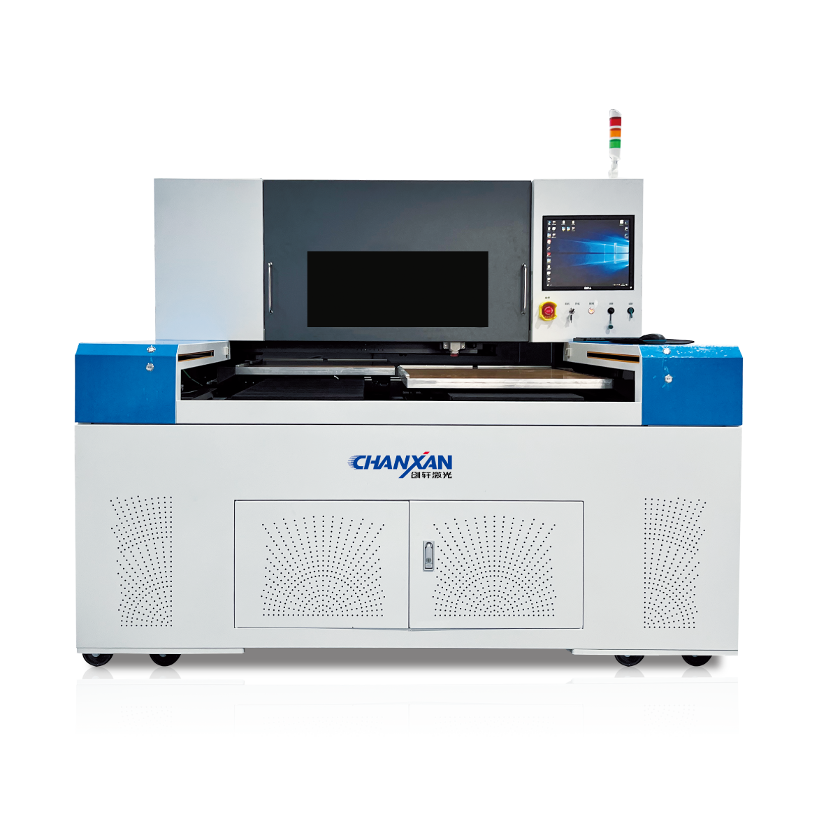
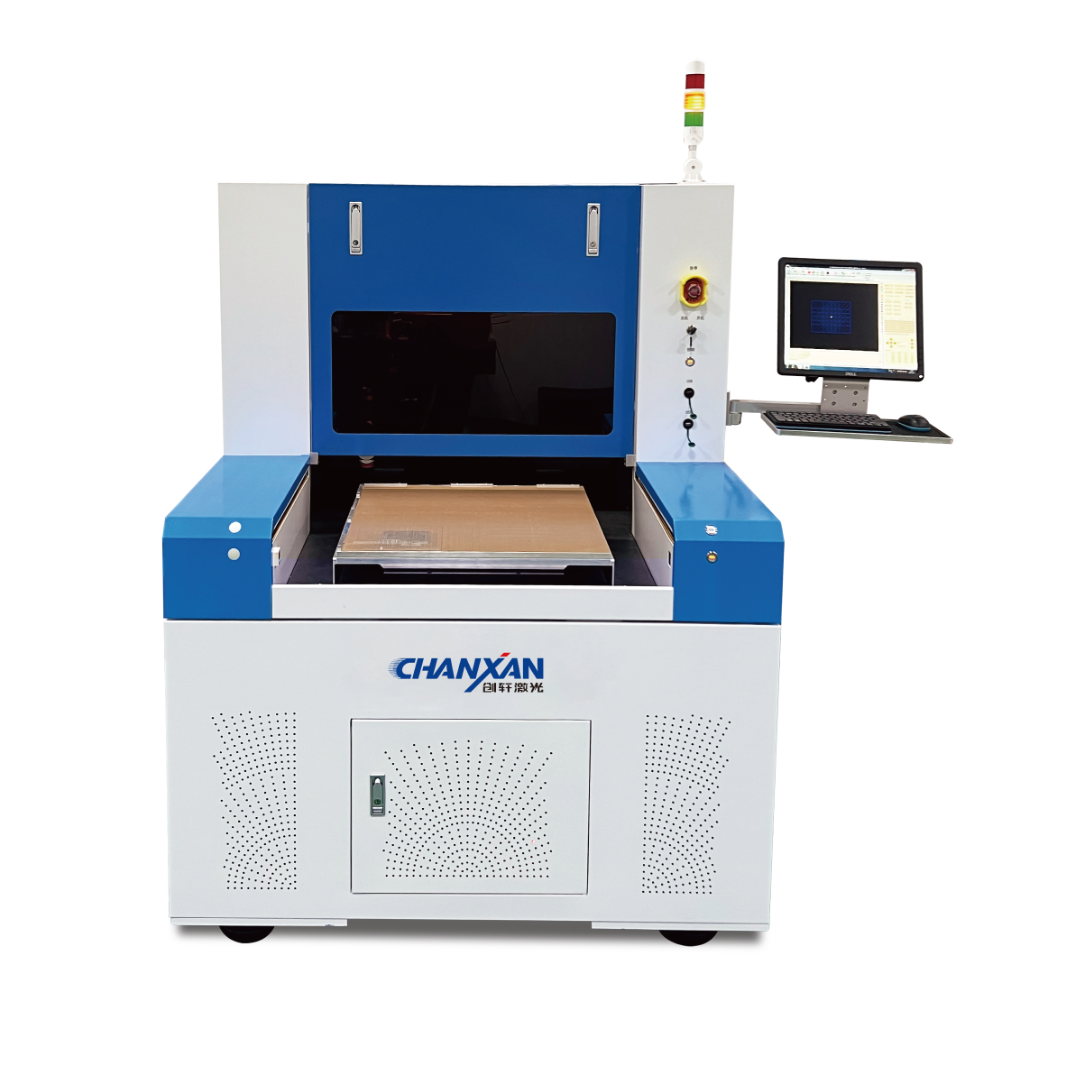
Chanxan Laser provides integrated laser processing systems that combine high‑performance UV picosecond sources with precision motion platforms and advanced process software. The picosecond laser system delivers the cold ablation, micron‑scale precision, and process stability required for demanding glass cutting applications, from UTG and cover glass to optical components and semiconductor packaging.
Get in touch with Chanxan Laser's application engineers to custom-tune system parameters and request a solution quote for your application.
Contact to Get a Quote| Free solution
Previous: LTCC Green Tape: A Complete Guide to Low-Temperature Co-Fired Ceramic Tape
Next: Micron‑Scale Glass Laser Ablation – How Ultrafast Lasers Enable Precision Glass Laser Cutting