Key Words: Silicon Wafer Dicing PCB Depaneling Glass Cutting
Home > News > Industry News
【Description】:
Discover Chanxan's UV Picosecond Laser Micro-Machining System for optical glass cutting. Achieve zero subsurface cracks, high precision, and cold ablation.
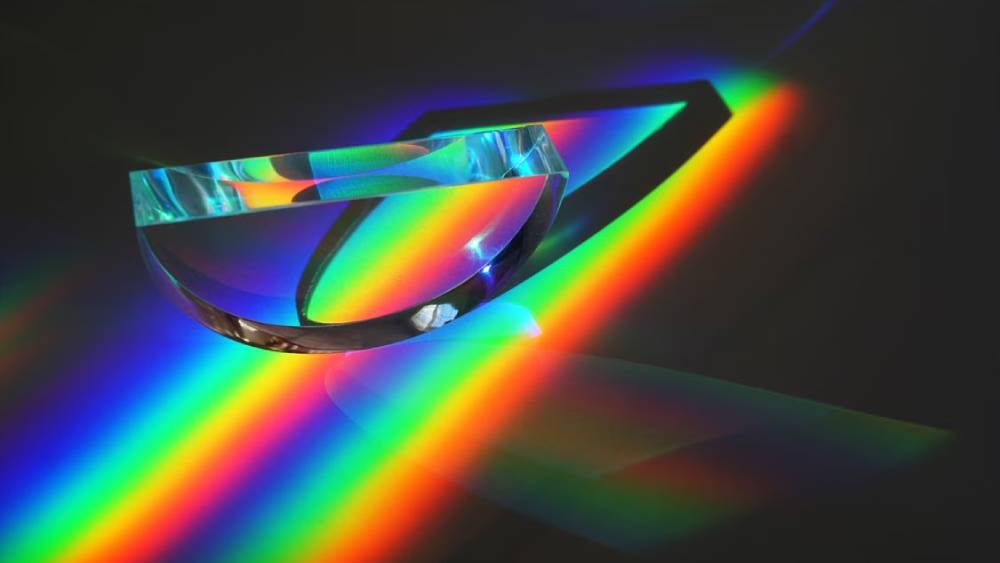
Optical glass is fundamentally different from standard glass. It is engineered for controlled refractive index, minimal internal stress, and exceptional optical homogeneity—properties that must be preserved during every manufacturing step.
Unlike soda‑lime or borosilicate glass, optical glass is used in applications where surface quality is mission‑critical. A scratch, chip, or subsurface crack in a lens or optical window scatters light, reduces transmission, and degrades image quality. In high‑end camera optics, photonic devices, or medical imaging systems, such defects render the component unusable.
Traditional cutting methods—mechanical sawing, diamond scribing, or waterjet—inevitably introduce surface damage. Optical components require:
Extremely low surface damage – no chips, no scratches, no subsurface cracks.
High dimensional accuracy – typically ±10–20 µm for precision assemblies.
Excellent edge quality – smooth edges that can be ground, polished, or bonded without delamination.
Ultrafast laser cutting (UV picosecond and femtosecond) has emerged as the only method that delivers optical‑grade edge quality without compromising the material's intrinsic properties. This article provides a focused guide on optical glass laser cutting—its applications, challenges, and practical processing considerations.
| Property | Optical Glass | Standard Soda‑Lime Glass | Implication for Cutting |
|---|---|---|---|
| Refractive index tolerance | ±0.0005 (precision grade) | ±0.01 | Any edge defect that alters local stress can affect optical path—must be avoided. |
| Internal stress | <5 nm/cm (Strain point) | Not specified | Thermal input from cutting must be minimal to avoid introducing stress birefringence. |
| Surface quality | Requires scratch‑free surfaces | Tolerates minor defects | Cutting must not produce scratches, chips, or subsurface damage. |
| Coefficient of thermal expansion | 5–12 ×10⁻⁶/K (varies by grade) | 9 ×10⁻⁶/K | Thermal shock sensitivity varies; requires controlled ablation. |
| Hardness | 400–650 HV | 450–500 HV | Similar range but optical grades are more sensitive to subsurface damage. |
| Glass Type | Examples | Key Characteristics | Typical Applications |
|---|---|---|---|
| Crown glass | BK7, N‑BK7, K‑BAL | Low dispersion; high transmittance | Lenses, prisms, windows for visible to near‑IR. |
| Flint glass | SF, F‑series | High dispersion; high refractive index | Achromatic doublets, photographic lenses. |
| High‑index glass | LASF, S‑LAH, S‑TIH | Refractive index >1.7 | Compact lens systems, high‑performance cameras. |
| Low‑dispersion glass | FK, S‑FPL, FCD | Anomalous partial dispersion | Telephoto lenses; microscope objectives. |
| Silica‑based | Fused silica, Suprasil, Infrasil | High UV‑IR transmission | UV optics, semiconductor lithography, astronomy. |
| Application | Components | Cutting Requirement |
|---|---|---|
| Photographic lenses | Lens elements (spherical, aspherical) | Precision cutting of lens blanks; edge quality essential for centring and coating adhesion. |
| Mobile phone cameras | Thin lens elements for compact modules | High‑volume precision cutting; ultra‑small dimensions; smooth edges. |
| CCTV and industrial lenses | Fixed focal length and zoom lenses | Consistent edge quality for automated assembly. |
| Medical endoscopy | Miniature lens assemblies | Ultra‑precision cutting; biocompatible edges. |
Why laser cutting is used: Mechanical cutting of lens blanks creates chipping that propagates during grinding and polishing, causing rejections. Laser cutting produces clean edges that reduce post‑processing loss.
| Application | Components | Cutting Requirement |
|---|---|---|
| Waveguides | Optical waveguides on glass substrates | Sub‑µm precision; smooth walls for low scattering loss. |
| Beam splitters | Splitter cubes | Precise dimensions; edge quality affects optical coupling. |
| Gratings | Diffraction gratings on glass | High precision; no subsurface damage. |
| Optical filters | Band‑pass; notch; dichroic filters | Smooth edges for mounting in filter holders. |
| Micro‑optics | Microlens arrays; diffractive optical elements | Complex shapes; ultra‑smooth edges. |
Why laser cutting is used: Photonic applications demand edge quality that only cold ablation can provide. Any thermal or mechanical damage increases insertion loss—a critical metric in optical networks.
| Application | Components | Cutting Requirement |
|---|---|---|
| Microscopy | Objective lenses; sample holders | High precision; no contamination. |
| Telescopes | Large‑diameter optical elements | Large‑area cutting; edge quality that preserves optical mounting. |
| Machine vision | Lenses for industrial inspection | Consistent quality across large production volumes. |
| Astronomical imaging | Large lenses and windows for telescopes | Large‑area precision cutting; minimal internal stress. |
| Defence optics | Periscopes; targeting optics | Reliability under extreme conditions; no edge defects. |
Why laser cutting is used: For large optics, the value of the material is extremely high. One cracked edge can destroy an entire component worth thousands of dollars. Laser cutting minimises risk.
| Application | Components | Cutting Requirement |
|---|---|---|
| High‑power laser windows | Beam splitter substrates | Smooth edges; no chips that could cause stress fracture under high optical power. |
| Gain media | Glass slabs for solid‑state lasers | Precision cutting; no residual stress. |
| Output couplers | Partial reflectors | High precision; no defects that could affect beam profile. |
| Protective windows | Optical shields | Large‑area cutting; mechanical strength. |
Why laser cutting is used: High‑power laser optics are sensitive to any surface defect that can initiate optical damage. UV ps laser cutting eliminates subsurface defects that would otherwise act as damage initiation sites.
For optical glass, the most important quality metric is subsurface damage (SSD).
| Defect Type | Mechanical Cutting | UV Picosecond Laser Cutting |
|---|---|---|
| Subsurface cracks | Common – 30–100 µm deep | None – cold ablation preserves crystal structure. |
| Edge chipping | Common – visible under 20× | None – non‑contact process. |
| Residual stress | High – from mechanical force | None – no thermal or mechanical stress. |
| Surface roughness | Ra >3 µm | Ra <0.5 µm |
| Optical quality | Requires extensive polishing to remove defects | Often acceptable for direct use. |
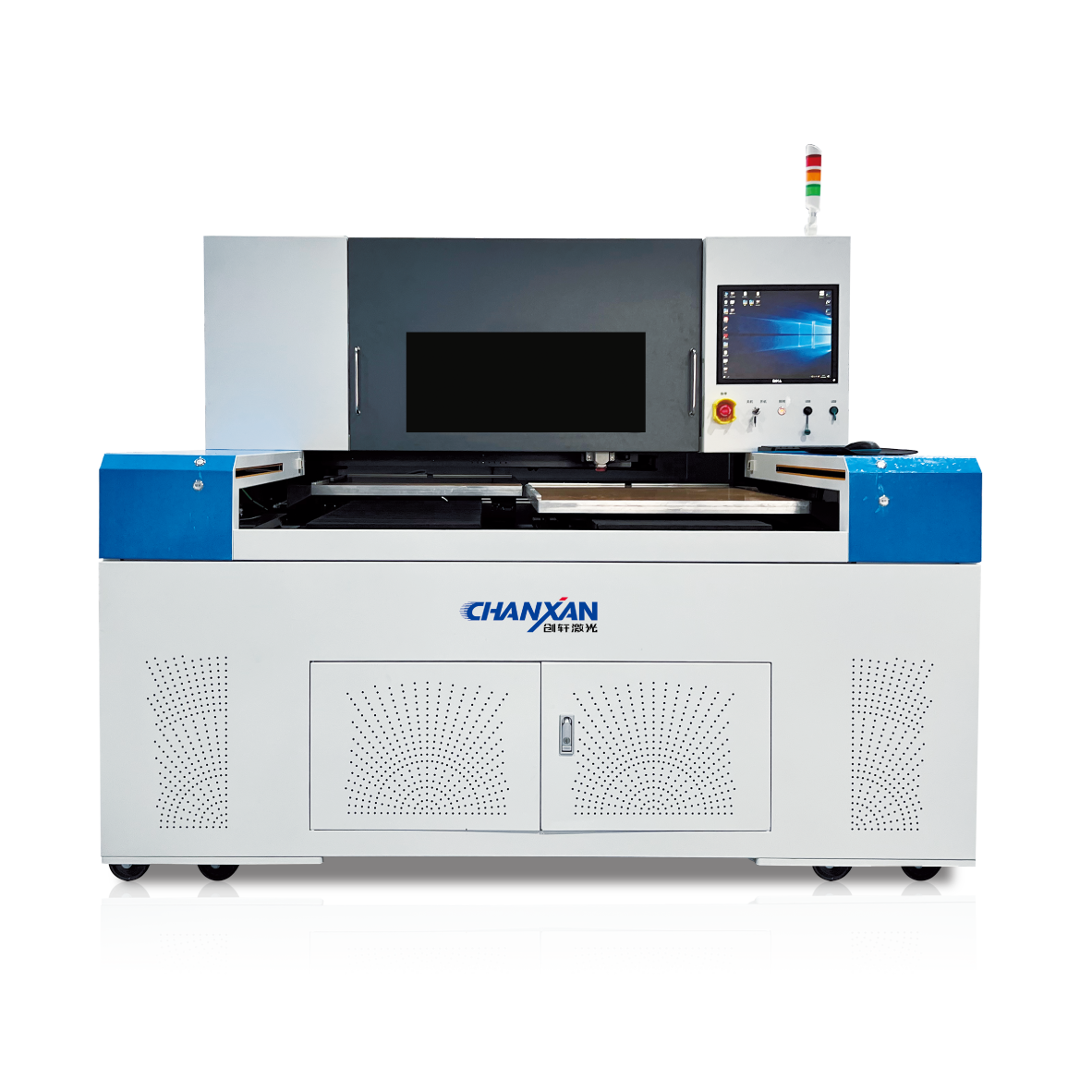
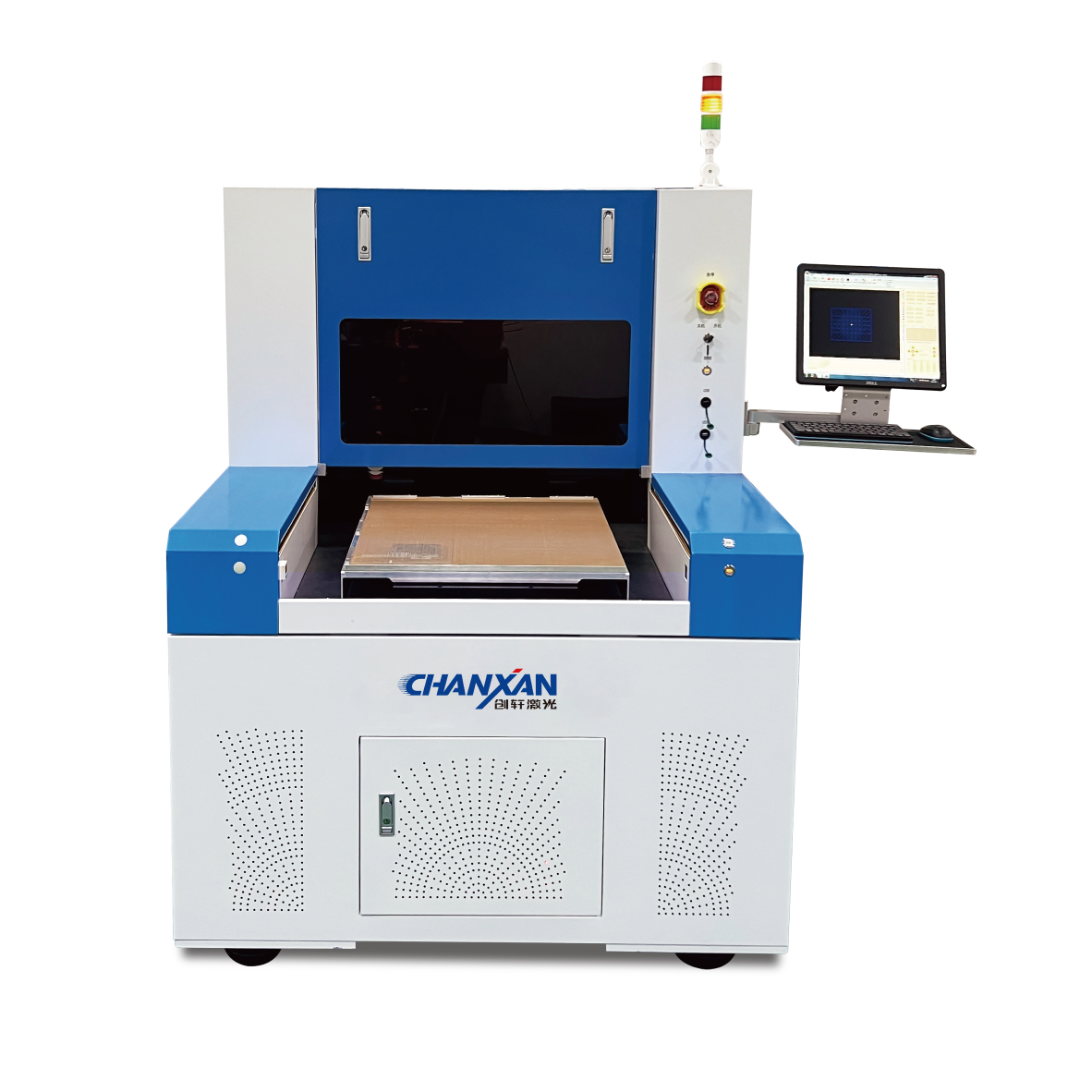
Chanxan Laser provides the UV Picosecond Laser Micro‑Machining System—specifically designed for high‑precision cutting of optical glasses.
| Parameter | Specification | Why It Matters for Optical Glass |
|---|---|---|
| Laser type | UV Picosecond (355 nm) | Strong absorption; enables cold ablation without thermal damage. |
| Pulse width | <10 ps | Eliminates subsurface damage—critical for optical applications. |
| Average power | 30W | Sufficient for high‑throughput cutting of optical glass. |
| Processing accuracy | ≤20 µm | Meets the tight tolerances of optical assemblies. |
| X/Y repeatability | ±2 µm | Consistent part‑to‑part quality. |
| Working area | 600 mm × 500 mm | Supports large panels and high‑volume production. |
| Platform | Granite base + linear motors | Vibration‑free; long‑term precision. |
| CCD alignment | Auto‑recognition | Accurate cut placement; compensates for panel position. |
| Focus tracking | Dynamic Z‑axis | Compensates for part warpage; maintains focus for consistent edge quality. |
| Software | Self‑developed; DXF/DWG import | Rapid job changeover; process database. |
| Free solution
Previous: Aluminosilicate Glass Laser Cutting – Precision Processing for Strengthened Cover Glass
Next: Quartz Glass Laser Cutting – Precision Processing Solution