Key Words: Silicon Wafer Dicing PCB Depaneling Glass Cutting
Home > News > Industry News
【Description】:
Practical guide to avoiding thermal damage and debris in LTCC laser via formation. Learn HAZ reduction, parameter tuning, and cleaning for clean, reliable vias.
Laser drilling of LTCC green tape is a mature process, but two persistent defects continue to challenge even experienced process engineers: thermal damage (manifesting as an oversized heat‑affected zone, binder degradation, or micro‑cracks) and debris contamination (recast material, molten droplets, or loose particles on via walls and surrounding surfaces). Both defects directly impact yield, via resistance, and long‑term reliability. They are also frequently interrelated—excessive heat generates more molten debris, while inadequate debris removal traps heat in the via.
| Symptom | Appearance | Likely Cause |
|---|---|---|
| Discoloured ring | Darkened halo surrounding the via, extending 10–50 μm from the edge | Binder burn‑out due to excessive heat; classic HAZ |
| Glassy or vitrified edge | Shiny, smooth appearance on the via wall or rim | Melting and re‑solidification of the glass‑ceramic matrix |
| Micro‑cracks | Fine, hairline fractures radiating from the via edge | Thermal stress during rapid heating/cooling cycles |
| Delamination | Separation between green tape layers near the via | Heat‑induced binder degradation at the interface |
| Via wall roughness | Irregular, jagged, or wavy wall surface | Recast layer or incomplete ablation |
| Debris field | Fine particles or molten droplets on the surface around the via | Ejection of molten material during drilling |
While thermal damage and debris often occur together, they have different root causes and require different corrective actions:
Thermal damage is a subsurface or edge phenomenon. It is caused by excessive heat input and is mitigated by reducing pulse energy, lowering repetition rate, or changing pulse duration.
Debris is a surface phenomenon. It is caused by inefficient material ejection and is mitigated by improving gas assist, adjusting scan strategy, or adding cleaning steps.
A via can exhibit severe thermal damage with no visible debris (if gas assist is excellent), or heavy debris with minimal thermal damage (if pulse energy is well‑controlled but ejection is poor). Accurate diagnosis requires distinguishing between the two.
Thermal damage is fundamentally a problem of heat accumulation. The goal of parameter tuning is to deliver enough energy to ablate the green tape efficiently, while allowing sufficient time for heat to dissipate between pulses. This section provides a systematic approach to identifying and correcting the parameters most likely to cause thermal damage.
Symptom: Discoloured ring, glassy edge, micro‑cracks.
Diagnosis: Pulse energy is too high. When a single pulse delivers more energy than is needed for ablation, the excess energy diffuses into the surrounding material as heat.
Corrective action:
Reduce pulse energy in 10% increments until the discoloured ring is minimised.
For nanosecond UV lasers (355 nm), typical pulse energies for LTCC green tape range from 10–50 μJ. Start at the lower end and increase only if drilling becomes incomplete.
For picosecond UV lasers, typical pulse energies range from 5–30 μJ.
Verification: After each adjustment, inspect the via under optical microscopy. The discoloured ring should diminish without causing incomplete penetration. If penetration fails before the ring disappears, the issue may be repetition rate or focus position, not pulse energy alone.
Symptom: Discoloured ring that worsens when drilling multiple vias in close proximity; heat build‑up in high‑density arrays.
Diagnosis: The repetition rate is too high, delivering pulses faster than the material can cool. This is especially problematic when drilling multiple vias in sequence—each via adds to the residual heat from the previous one.
Corrective action:
Reduce repetition rate from, for example, 200 kHz to 100 kHz or 50 kHz.
If throughput is critical, consider skip‑drilling (drilling vias in a non‑sequential order) to allow heat to dissipate between adjacent vias.
Alternatively, use burst mode (if available) to deliver energy in controlled packets rather than a continuous stream.
Verification: Drill a test array of 10×10 vias. Measure the HAZ of the first via and the last via. If the HAZ of the last via is significantly larger, heat accumulation is occurring. Reducing repetition rate or implementing skip‑drilling should equalise the HAZ across the array.
Symptom: Persistent HAZ even at low pulse energy and repetition rate.
Diagnosis: The pulse duration is too long. Nanosecond pulses (10–50 ns) allow heat to diffuse into the surrounding material during the pulse itself. Picosecond pulses (~10 ps) deposit energy faster than thermal diffusion can occur, resulting in a dramatically reduced HAZ.
Corrective action:
If the application requires the absolute minimum HAZ (e.g., <5 μm), consider switching from a nanosecond to a picosecond laser.
If nanosecond must be used, accept a HAZ of 10–20 μm and optimise other parameters to keep it at the lower end of this range.
Verification: Compare HAZ measurements from nanosecond and picosecond drilling on the same tape formulation. A picosecond laser typically reduces HAZ by 50–80% compared to nanosecond at equivalent ablation efficiency.
Symptom: Thermal damage concentrated at the via bottom or along the walls, with a relatively clean entry.
Diagnosis: The focus is positioned too deep, causing the beam to converge at a point where material has already been removed, leading to excessive heating of the remaining material.
Corrective action:
Adjust focus position to mid‑depth (40–60% of tape thickness) or use dynamic focus to maintain optimal beam position throughout drilling.
For thin tapes (<100 μm), focus at the surface or slightly above.
For thick tapes (>200 μm), use a longer depth‑of‑focus lens (lower NA) and consider multi‑pass drilling.
Verification: Drill a series of vias at different focus positions and measure the HAZ at the entry, middle, and exit. The optimal focus position produces the most uniform HAZ distribution.
Symptom: Localised thermal damage at the via edge, often with a glassy rim.
Diagnosis: Percussion drilling (stationary beam) concentrates all pulse energy in one spot, causing localised overheating. Trepanning or helical drilling distributes energy over a larger area, reducing peak temperature.
Corrective action:
For vias >75 μm diameter, switch from percussion to trepanning or helical drilling.
For vias <75 μm, percussion may be necessary, but reduce pulse energy and use multi‑pass drilling to allow cooling between passes.
Verification: Compare the edge quality of percussion‑drilled and trepanned vias. Trepanned vias typically exhibit a smoother, less discoloured rim.
Debris is generated when molten or vaporised material is not efficiently ejected from the via. It can deposit on the via walls, the surrounding surface, or the underside of the tape. Effective debris management combines in‑process ejection with post‑process cleaning.
Gas Assist:
Coaxial gas assist (gas flowing through the same nozzle as the laser beam) is the most common method. It helps eject debris upward and away from the via.
For high‑aspect‑ratio vias, a pulsed gas jet synchronised with the laser pulses can significantly improve debris removal. The pulse of gas is delivered immediately after each laser pulse, when the ejected material is still airborne.
Side‑jet gas assist (gas directed at an angle to the via) can be more effective for large vias but may interfere with the laser beam if not carefully positioned.
Recommended gas parameters:
Gas type: Compressed air or nitrogen (nitrogen reduces oxidation).
Pressure: 0.2–0.5 MPa (2–5 bar).
Flow rate: 10–30 L/min, depending on via size and depth.
Vacuum Extraction:
A vacuum nozzle positioned 5–10 mm from the drilling site captures airborne debris before it settles.
For high‑density arrays, a combination of gas assist and vacuum extraction is most effective.
Scan Strategy:
Multi‑pass drilling allows debris to evacuate between passes. After each pass, a brief pause (10–50 ms) allows the gas assist to clear the via.
Helical drilling creates a spiral path that helps debris travel up and out of the via.
Even with optimal in‑process debris control, some residue may remain. Post‑process cleaning ensures that vias are completely free of debris before via filling and lamination.
Ultrasonic Cleaning:
Procedure: Immerse the drilled green tape in a suitable solvent (e.g., isopropyl alcohol, ethanol, or a proprietary green tape cleaner). Apply ultrasonic agitation for 2–5 minutes. Rinse with fresh solvent and dry with filtered air or nitrogen.
Effectiveness: Ultrasonic cleaning removes loose debris and organic residues from the via walls and surface.
Caution: Prolonged ultrasonic exposure can cause edge chipping in fragile green tapes. Limit to 5 minutes and use the lowest power setting that achieves cleanliness.
Plasma Cleaning:
Procedure: Use an oxygen plasma to remove organic contaminants and oxidise residual carbon. Typical parameters: 100–200 W, 5–10 minutes, oxygen flow 50–100 sccm.
Effectiveness: Plasma cleaning is highly effective for preparing via walls for metallisation. It removes the last traces of organic binder and leaves a hydrophilic surface that promotes paste adhesion.
Caution: Plasma cleaning requires specialised equipment and is typically used for high‑reliability applications.
Laser Clean‑Up Pass:
Procedure: After drilling, run a low‑energy laser pass over the via walls. The energy should be below the ablation threshold for the ceramic but sufficient to dislodge loosely adhered debris.
Effectiveness: This is a dry process that can be integrated into the drilling program. It is particularly useful for removing recast material.
Caution: Over‑application can cause additional thermal damage. Use with care and verify results microscopically.
Micro‑Abrasive Cleaning:
For stubborn debris, a fine abrasive slurry (e.g., alumina particles in water) can be gently flushed through the vias. This is followed by thorough rinsing and drying.
This method is effective but requires careful control to avoid enlarging the via or damaging the green tape surface.
Thermal damage and debris are not inevitable consequences of laser via drilling in LTCC green tape. With careful attention to pulse energy, repetition rate, focus position, scan strategy, and cleaning protocols, manufacturers can achieve clean, vertical via walls with minimal HAZ and zero debris contamination.
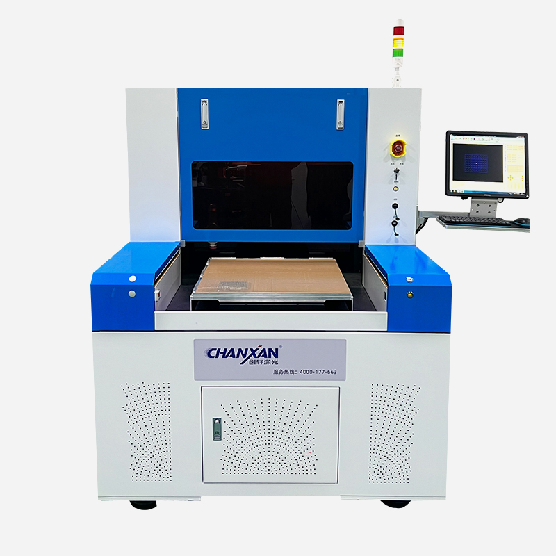
Chanxan Laser provides comprehensive solutions for LTCC via formation, including:
UV nanosecond and picosecond laser systems with adjustable pulse energy, repetition rate, and burst mode for optimal thermal control.
Integrated gas assist and vacuum extraction for in‑process debris removal.
Process development support to characterise your specific green tape formulation and develop a robust, repeatable drilling recipe.
Post‑process cleaning recommendations and equipment for ultrasonic, plasma, or laser clean‑up.
Whether you are troubleshooting an existing process or developing a new LTCC via drilling application, Chanxan Laser offers the technology, expertise, and support to achieve defect‑free results.
| Free solution
Previous: Laser Processing for Automotive‑Grade LTCC Substrates: 77 GHz Radar and Power Electronics Packaging
Next: High‑Aspect‑Ratio LTCC Via Drilling: Laser Process Optimisation Guide