Key Words: Silicon Wafer Dicing PCB Depaneling Glass Cutting
Home > News > Industry News
【Description】:
A comprehensive guide on Ultra-Thin Glass (UTG) material characteristics, foldable applications, ultrafast laser processing requirements, and Chanxan's Picosecond Laser cutting solution.
Article Directory /
Ultra-Thin Glass (UTG) has emerged as the enabling material for the foldable device revolution. With thicknesses ranging from 20 to 100 micrometres—comparable to a human hair—UTG combines the optical clarity, scratch resistance, and premium feel of glass with the flexibility required for foldable displays.
The rapid adoption of foldable smartphones, flexible OLED panels, and wearable devices has made UTG one of the most strategically important materials in consumer electronics. However, its extreme thinness also makes it exceptionally challenging to process. Traditional mechanical cutting methods inevitably cause edge chipping and micro-cracks; thermal laser processes introduce heat-affected zones that compromise fold durability.
Ultrafast laser cutting—specifically using UV picosecond (ps) lasers—has become the industry-standard solution for UTG processing. It delivers crack-free, smooth edges that preserve the glass integrity required for hundreds of thousands of fold cycles.
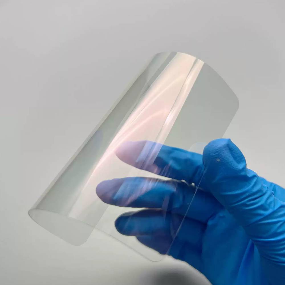
Ultra-Thin Glass is a chemically strengthened alkali-aluminosilicate glass manufactured in thicknesses of 20–100 µm. It is produced through a fusion draw process, followed by chemical strengthening (ion-exchange) to enhance surface compressive stress and flexibility.
| Parameter | Typical Value | Implication for Processing |
|---|---|---|
| Thickness | 20–100 µm | Requires non-contact processing; any mechanical force risks fracture. |
| Optical transparency | >92% (visible range) | UV wavelengths (355 nm) are absorbed at the surface; IR passes through. |
| Surface roughness (Ra) | <1 nm (as-manufactured) | Must be preserved; laser processing must not degrade surface quality. |
| Surface hardness | 6–7 Mohs | Scratch-resistant; mechanical scribing is difficult and damaging. |
| Bend radius (minimum) | 2–5 mm (at 50 µm) | Edge quality directly impacts achievable bend radius. |
| Fold durability | >200,000 cycles (with proper edge treatment) | The critical reliability metric; edge defects reduce this significantly. |
| Property | UTG | Polymer Film (PI/CPI) | Why UTG Is Preferred |
|---|---|---|---|
| Optical clarity | >92% transmission | 85–90% (often with yellow tint) | UTG provides superior brightness and colour accuracy. |
| Surface hardness | 6–7 Mohs | 2–3 Mohs | UTG resists scratches without additional coatings. |
| Fold durability | >200,000 cycles | Varies; often degrades | UTG offers proven long-term reliability. |
| Dimensional stability | CTE ~8 ppm/°C | Higher expansion | UTG maintains alignment across temperature changes. |
| Gas barrier | Impermeable | Permeable | UTG provides better OLED protection. |
Note on Laser Processing: UTG's high transparency requires specific laser wavelengths (UV) and nonlinear absorption mechanisms for effective processing—this is detailed in Section 4.
At 20–100 µm thickness, UTG behaves fundamentally differently from thicker glass:
| Factor | Explanation | Processing Implication |
|---|---|---|
| Low flexural rigidity | The glass bends easily but concentrates stress at defects. | Any edge defect becomes a failure point during folding. |
| No bulk to absorb defects | A micro-crack that is harmless in 1 mm glass propagates catastrophically in UTG. | Edge quality must be pristine—no subsurface damage tolerated. |
| High surface-to-volume ratio | Surface defects dominate mechanical behaviour. | Surface quality must be preserved during processing. |
| Supplier | Product Name | Typical Thickness | Key Properties |
|---|---|---|---|
| Schott | AS 87 eco UTG | 30–100 µm | High strength; low CTE; proven in foldable devices. |
| Corning | Gorilla Glass UTG | 30–100 µm | High damage resistance; widely adopted. |
| AGC | Dragontrail UTG | 30–100 µm | Good strength and optical quality. |
| NEG | DINEX UTG | 20–100 µm | High reliability; good ion-exchange response. |
The primary application for UTG is foldable smartphones. These devices require:
Cover glass for main foldable display and external cover screen.
Curved edge designs—rounded corners and contoured edges.
Notch cutting—camera holes, speaker cutouts, sensor apertures.
High precision—part-to-part uniformity for automated assembly.
Beyond foldable phones, UTG is used as:
OLED encapsulation cover—impermeable barrier against moisture/oxygen.
Display substrate—stable, flat base for OLED deposition.
Touch panel cover—superior hardness and clarity over polymer.
Laser processing requirement: Flexible OLED fabrication requires precise cutting of UTG sheets into specific panel sizes—often with complex geometries for device integration.
Smartwatches, fitness trackers, and AR/VR headsets increasingly adopt UTG:
| Device | UTG Application | Laser Processing Need |
|---|---|---|
| Smartwatches | Curved display covers | Curved edge cutting with high precision. |
| Fitness trackers | Small-form-factor covers | Precision cutting of small parts. |
| AR/VR headsets | Optical windows and waveguides | Ultra-smooth edges for optical clarity. |
UTG is used in advanced optical systems where thinness and clarity are valued:
| Application | UTG Use | Processing Need |
|---|---|---|
| Optical filters | Ultra-thin substrates | Edge smoothness minimizes light scattering. |
| Micro-optics | Thin glass for lenses | Precision shape; edge quality affects optical performance. |
| Waveguide substrates | AR/VR optical combiners | High-quality edges for optical coupling. |
For UTG, the cutting method determines whether the final product survives folding or fails. Here is the essential comparison:
| Method | Why It Fails (or Succeeds) | Verdict |
|---|---|---|
| Mechanical scribe & break | Mechanical force creates micro-cracks at the edge. In 50 µm glass, these cracks propagate immediately—yield loss >80%. | Not viable |
| CO₂ / IR laser | Glass is transparent to these wavelengths; energy passes through without cutting. | Not viable |
| UV nanosecond laser | Some thermal component remains. HAZ of 5–10 µm weakens the edge—fold cycles drop to 50,000–100,000. | Marginal |
| UV picosecond laser | Pulse width (<10 ps) is shorter than thermal diffusion time. No heat, no cracks, no HAZ. Edge strength preserved. | The standard |
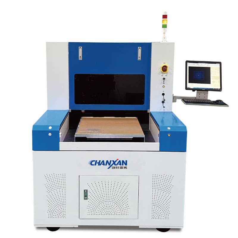
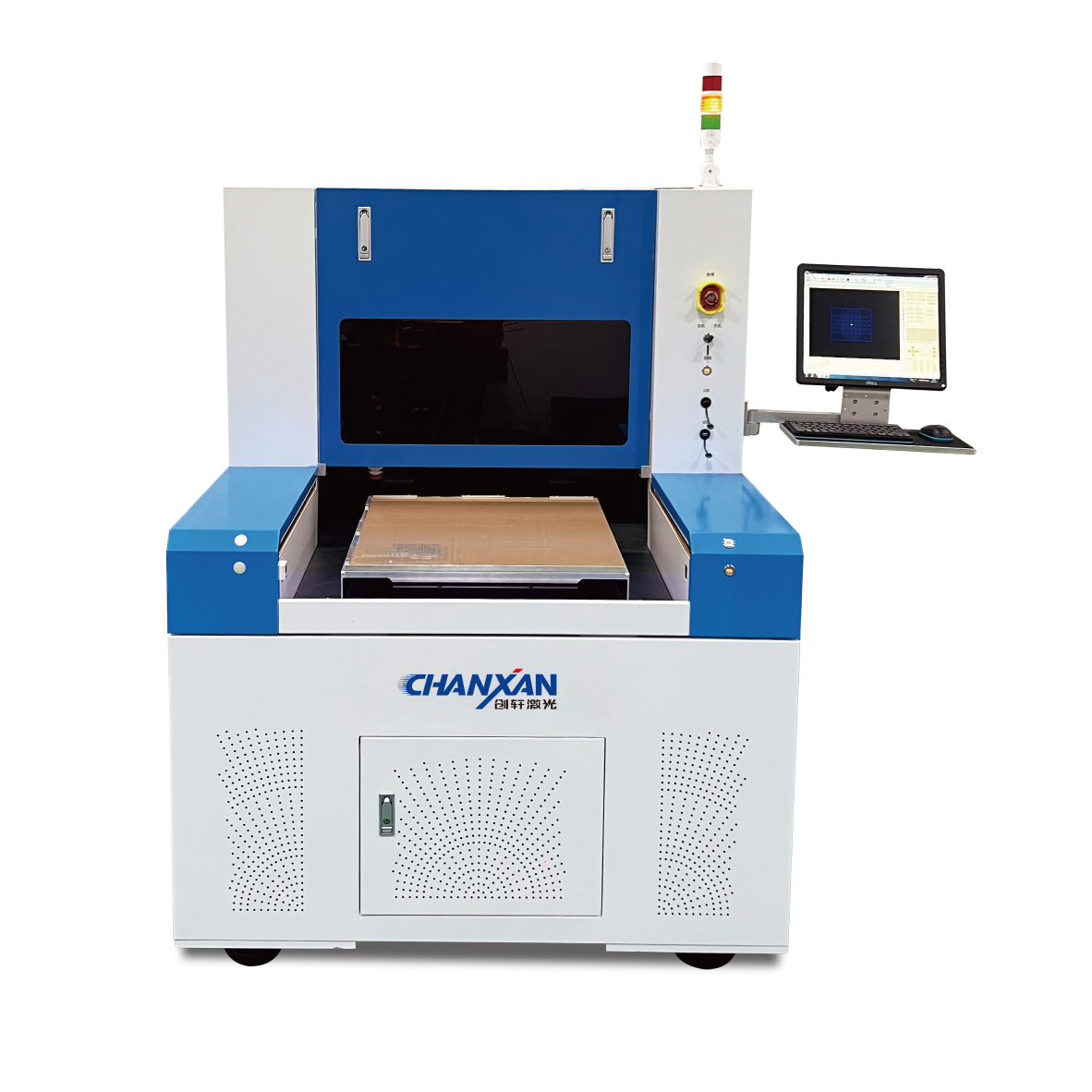
Chanxan Laser provides the UV Picosecond Laser Micro-Machining System—a production-ready solution for UTG cutting.
| Parameter | CS‑0605‑V‑A Specification | Why It Matters for UTG |
|---|---|---|
| Laser type | UV Picosecond (355 nm) | Strong absorption in UTG; cold ablation. |
| Pulse width | <10 ps | Zero thermal damage; enables >200,000 fold cycles. |
| Average power | 30W | High throughput—fast UTG cutting. |
| Spot size | 20 µm | Fine kerf control; sharp corners and curves. |
| Processing accuracy | ≤20 µm | Meets foldable display tolerances. |
| X/Y repeatability | ±2 µm | Consistent part-to-part quality. |
| Working area | 600 mm × 500 mm | Large panels; high material utilisation. |
| Platform | Granite base + linear motors | Vibration-free; long-term precision. |
| CCD alignment | Auto-recognition | Accurate cut placement; compensates for panel position. |
| Focus tracking | Dynamic Z-axis | Compensates for UTG warpage. |
| Software | Self-developed; DXF/DWG import | Rapid job changeover; process database. |
| Free solution
Previous: Borosilicate Glass Laser Cutting – How to Cut Borosilicate Glass Guide
Next: Ultrafast Laser Precision Cutting and Marking of Microscope Glass Slides – A Practical Guide