Key Words: Silicon Wafer Dicing PCB Depaneling Glass Cutting
Home > News > Industry News
【Description】:
How 3D five-axis CO2 laser cutting systems deliver precise, crack-free, and perpendicular edge processing on curved plastics, automotive interior trim, and complex 3D components.
Modern manufacturing relies heavily on complex three-dimensional parts: injection-molded automotive interior panels, curved helmet shells, and irregular plastic housings for electronics. These parts cannot be processed by 3-axis laser cutters without compromising cut quality, accuracy, or production speed. This is where the 3D five-axis laser cutting machine steps in.
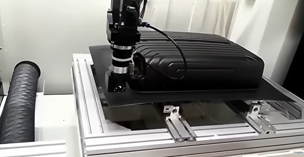
To understand the value of five-axis technology, we must first recognize the inherent limitations of a 3-axis system when dealing with non-flat workpieces.
A standard 3-axis laser cutting head remains fixed in a vertical orientation. It can move left/right (X), front/back (Y), and up/down (Z) to follow the general contour, but the laser beam always points straight down. This works perfectly for flat sheets, but on a curved 3D surface:
| 3-Axis Behavior on Curved Surfaces | Resulting Defect |
|---|---|
| The beam hits sloped sections at an oblique angle instead of perpendicularly. | Tapered cut faces – the edge is not square, compromising part fit and weld/seal quality. |
| The effective kerf width changes as the angle of incidence changes. | Inconsistent kerf – some sections cut wider than others, affecting dimensional accuracy. |
| The nozzle may collide with the workpiece on steep contours. | Physical interference – the machine cannot complete the cut safely or at all. |
| Features like holes must be cut vertically. | Misaligned holes – on curved surfaces, vertical holes are angled relative to the local surface, preventing flush mounting of components. |
In short, a 3-axis laser cutter simply cannot produce a square, accurate, and consistent cut on a 3D curved part. Any attempt results in parts that require extensive manual rework, sanding, or rejection.
A 5-axis system builds upon the three linear axes (X, Y, Z) by adding two rotational axes—typically a tilting axis (A) and a swiveling axis (C). This enables the cutting head to change its orientation in real-time, continuously adjusting the laser beam to remain perfectly perpendicular to the workpiece surface throughout the entire cutting path.
Here is a step-by-step breakdown of how the system processes a complex plastic or automotive part:
3D CAD Model Import (or DMP Teaching): The cutting path is defined. For high-volume production, the 3D model is imported into CAM software to generate the 5-axis toolpath. For flexible, low-volume, or prototype runs, a DMP (Direct Motion Programming) Teaching System allows an operator to simply guide the cutting head along the part's edge; the machine records the trajectory and automatically generates the program.
Precise Part Positioning: The workpiece is placed in a simple, low-cost positioning fixture. Because the laser exerts no mechanical force, fixtures do not need to withstand heavy cutting loads—they only need to hold the part securely in place.
Simultaneous 5-Axis Motion: During the cutting cycle, all five axes move together in a coordinated manner. As the head follows the trim line around a curved helmet shell, the A and C axes constantly rotate to keep the beam normal (perpendicular) to the surface at each point.
Contour Trimming and Hole Cutting: In a single, uninterrupted pass, the machine completes the full contour trimming of the part perimeter and cuts all required holes, slots, and openings—regardless of whether they are located on flat sections or steeply curved surfaces.
Finished Part Unload: The processed part is removed. The cut edges are smooth, square, and free of burrs, requiring no secondary deburring, sanding, or manual finishing before moving to assembly or painting.
For the specific application of cutting complex plastic and automotive interior parts, the predominant laser source is the CO₂ laser. CO₂ lasers operate at a wavelength (10.6 µm) that is readily absorbed by most non-metallic materials, delivering clean cuts with minimal heat-affected zones on materials like ABS, PC, PP, and acrylic.
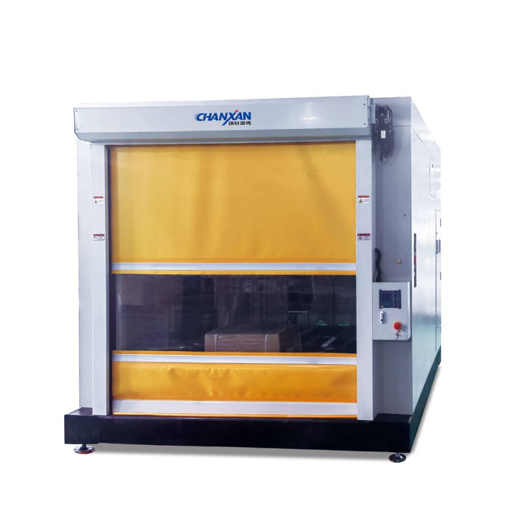
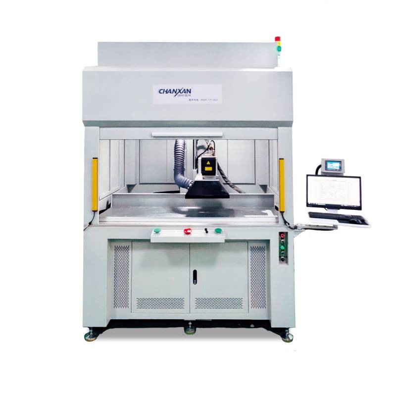
The Chanxan CW-3W1280 is designed with this core application in mind. Its standard configuration utilizes a CO₂ glass tube laser source, optimized for the high-quality cutting of plastic components, molded parts, and composite materials.
When evaluating a system, always match the laser source to your actual material mix—do not pay for a capability you will never use, and do not assume a machine handles all materials equally well without verified test results.
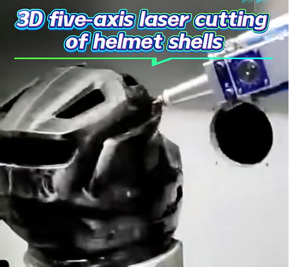
The 3D five-axis laser cutting process is effective on a specific, validated set of materials commonly found in injection-molded and thermoformed parts. Chanxan Laser's CW-3W1280 3D five-axis laser cutting machine is engineered to cut the following materials with documented consistency:
| Material Category | Specific Materials | Typical Application |
|---|---|---|
| Engineering Plastics | ABS, PC (Polycarbonate), PC/ABS blends | Automotive interior panels, helmet shells |
| Polyolefins | PP (Polypropylene), PE (Polyethylene) | Bumper components, ducting, consumer housings |
| Technical Polymers | PA (Nylon), PET, PBT | Under-hood components, structural brackets |
| Elastomers & Flexible Plastics | TPU, PUR | Soft-touch trim, seals, padding components |
| Other Non-Metallics | PVC, Acrylic (PMMA) | Interior trim, display covers, lighting housings |
Important Principle: Only materials that have been verified through actual processing tests are listed here. It is always recommended to conduct a free sample test (offered by Chanxan Laser) before committing to a purchase, as real-world cut quality depends on material thickness, geometry, and specific formulation.
The true value of a 3D five-axis laser cutting machine is best understood by looking at actual, tangible parts it can process in a production environment. These applications require the combination of contour trimming and surface feature cutting that only 5-axis technology can deliver.
Dashboard panels: Trimming the perimeter and cutting speaker grille openings on a curved, dual-layer plastic assembly.
Door trim panels: Cutting armrest contours, switch panel openings, and ambient light slots—all in one clamping.
Center console components: Processing complex curves, storage compartment cutouts, and mounting features.
Nozzles and fluid connectors: Trimming sprues and cutting precise side openings that must mate with other components.
Complex housings (e.g., electronics enclosures): Cutting access ports, ventilation slots, and mounting tabs on parts with ribs, bosses, and curved walls.
Helmet shells (cycling, motorcycling, industrial): Full perimeter trimming and drilling of ventilation holes across the crown and side curvature.
Sporting goods (e.g., shoe heels, protective gear): Trimming irregular 3D contours and perforating for breathability.
Blister-pack and toy components: High-speed cutting of thin-walled 3D plastic forms.
Any semi-finished plastic part with an irregular, non-planar shape that requires precise edge finishing and cut-out features.
For manufacturers looking to adopt this technology for plastic and automotive part processing, Chanxan Laser offers a proven, practical solution with the CW-3W1280 3D Five-Axis Laser Cutting Machine.
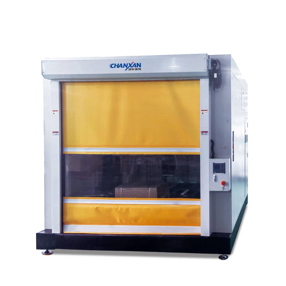
This system is engineered specifically to address the challenges of 3D part manufacturing:
True five-axis linkage ensures perfect beam-to-surface perpendicularity on complex curves.
The DMP Teaching System significantly lowers the barrier to entry—operators can teach complex paths without needing advanced G-code or CAM programming skills, making model changes quick and cost-effective.
Cost-effective fixturing reduces tooling investment and simplifies changeovers.
Comprehensive technical training and 24-hour after-sales support ensure your production line stays operational with minimal downtime.
For reference, the Chanxan 5-axis laser cutting machine offers the following verified performance parameters:
| Parameter | Specification | Practical Interpretation |
|---|---|---|
| Positioning Accuracy | < 0.2 mm | Ensures precise edge alignment and hole placement, critical for mounting interfaces. |
| Maximum Curve Speed | 6000 mm/min | High-speed contour following reduces cycle time for complex paths. |
| Cutting Speed | 0 – 4000 mm/min (adjustable) | Speed is optimized per material and thickness to balance quality and throughput. |
| Work Envelope (L × W × H) | 1200 × 800 × 500 mm | Accommodates medium-to-large automotive interior panels and helmet shells. |
| Laser Power Control | 0 – 100% continuous adjustment | Allows fine-tuning of energy input to minimize heat-affected zone on sensitive plastics. |
| Cutting Principle | DMP Teaching-based or Offline CAM | Offers extreme flexibility—teach the path manually or import from 3D CAD. |
Contact Chanxan Laser today for a free sample test and tailored solution quote.
Get a Free Quote & Sample Test| Free solution