Key Words: Silicon Wafer Dicing PCB Depaneling Glass Cutting
Home > News > Industry News
【Description】:
Discover the technical difference between CO2 and UV laser film cutting machines. Learn how to minimize HAZ, avoid carbonization, and achieve burr-free film cutting.
The explosive growth of modern industrial sectors has placed immense pressure on manufacturers to design smaller, lighter, and more complex devices. From consumer electronics to energy sectors, utilizing a high-efficiency film laser cutting machine has transitioned from an advanced upgrade to a baseline production standard. However, selecting the optimal configuration—specifically evaluating UV laser vs CO2 laser technologies—remains a critical technical decision. Choosing an unoptimized wavelength can trigger catastrophic substrate failure, including heavy edge carbonization and delamination. This comprehensive guide delivers a scientifically verifiable analysis of UV laser vs CO2 laser for film cutting, detailing how pulse-width dynamics affect micro-machining quality, edge precision, and overall yield.
The fundamental processing divergence between a CO2 laser film cutting machine and a UV laser film cutting machine lies in how their light energy interacts with the molecular bonds of the targeted material.
CO2 Laser Processing Mechanics: A standard CO2 industrial source emits a far-infrared wavelength (typically 10.6μm). This wavelength operates entirely via thermal energy. The substrate absorbs the infrared photons, generating localized heat that rapidly elevates the material past its vaporization point. This infrared film laser cutting process is exceptionally fast and highly cost-effective for thick or non-reactive materials.
UV Laser Processing Mechanics: A solid-state UV source operates at a much shorter ultraviolet wavelength (typically 355nm). Instead of relying on raw heat, UV systems utilize high-energy photons to directly break the molecular bonds within the substrate. This specialized process, known as laser ablation of film materials, relies on photo-chemical disruption rather than thermal melting.
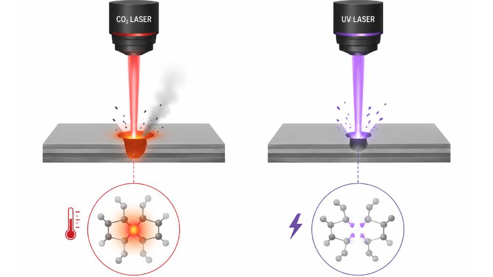
To understand how these wavelength characteristics translate into high-yield floor manufacturing, we must benchmark CO2 vs UV laser processing across primary performance dimensions:
| Feature | CO2 Laser Film Cutting Machine | UV Laser Film Cutting Machine |
|---|---|---|
| Wavelength | 10.6 μm (Far-Infrared) | 355 nm (Ultraviolet) |
| Ablation Mode | Thermal Melt & Vaporization | Photo-Chemical Bond Breaking (Cold Laser) |
| Heat-Affected Zone (HAZ) | Moderate to High (Visible localized melting) | Ultra-Low / Negligible (Micron-level control) |
| Minimum Spot Diameter | ~100 μm - 150 μm | ~10 μm - 20 μm (Precision Film Micro Machining) |
| Primary Risk Factors | Carbonization, edge bead, deformation | Slower linear speed on ultra-thick substrates |
Thin-film manufacturing requires versatile equipment capable of handling diverse chemical compositions without compromising layer integrity.
In flexible electronics manufacturing, polyimide film laser cutting demands zero mechanical or thermal distortion. When executing PI film cutting, a CO2 source frequently leaves a pronounced charred border due to the material's high thermal resistance. Conversely, a precision film laser cutting system leveraging a UV source cleanly cleaves the polyimide layers, making it the ideal selection for flexible electronics film cutting and high-density semiconductor packaging film processing.
For PET film laser cutting, optical clarity and flat edge profiles are non-negotiable. CO2 cutting often creates an elevated "edge bead" as molten material resolidifies at the border. A UV system eliminates this issue completely, ensuring pristine results during polymer film laser cutting for display film laser processing and medical film device cutting.
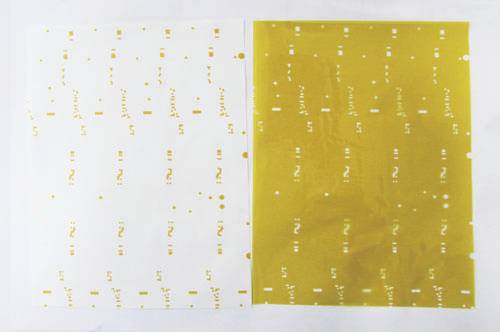
Transitioning from traditional mechanical stamping to an industrial film cutting laser equipment setup directly addresses the severe yield limitations of hard tooling while resolving specific material vulnerabilities.
Achieving Burr Free Film Cutting: When assessing laser cutting vs mechanical cutting for film, physical dies inevitably dull, creating tension fractures and edge deformations. A non-contact film cutting laser beam ensures consistent burr free film cutting throughout the entire life cycle of the production line.
Eliminating Delamination in Film Processing: Multilayer films are highly susceptible to inter-layer separation when exposed to physical stress or excessive heat. Implementing a precision strategy prevents delamination in film processing, protecting sensitive adhesive layers.
How to Reduce HAZ in Film Laser Cutting: Minimizing the Heat-Affected Zone is vital to prevent trace degradation. Advanced UV layouts vastly reduce HAZ in film laser cutting, achieving a localized heat footprint of less than 15μm. This enables micro-drilling and complex contouring close to active circuit architectures, offering a true film cutting without damage environment.
How to Avoid Carbonization in Film Laser Processing: For insulation layers, carbonized edges create conductive paths that cause electrical shorts. Utilizing short-pulse UV ablation allows operators to completely avoid carbonization in film laser processing, delivering maximum dielectric reliability for battery insulation film cutting and automotive insulation film processing.
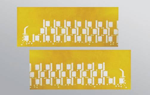
Both optical technologies hold definitive positions in modern industrial manufacturing lines. A precision CO2 laser system remains an excellent, high-throughput tool for rapid cutting of thick, single-layer sheets where microscopic thermal effects do not impact product functionality. However, when your engineering tolerances demand sub-micron accuracy, ultra-clean edge profiles, and zero thermal degradation, an advanced UV high precision film cutting solution represents the definitive industry standard for next-generation film applications.
| Free solution
Previous: Can Femtosecond Lasers Achieve 100% Carbonization-Free FPC Cutting?
Next: Laser Cutting vs Die Cutting for FPC Cutting: Which Is Right for Your Production?